The article I read is: Does anyone actually use digital audio players?
Short answer, yes - yes there are plenty of people that use digital audio players (DAPs).
You see, we DAP users tend to hide in our little alcove, hidden away from the rest of the world (unless you know where to look).
More seriously, it's true we are somewhat "far and few", but we do exist and we do buy DAPs. Most of us "hide" on audiophile sites like head-fi.org and go to expos like CanJam, but of course, some of us also don't.
I'll quit having fun now and actually rant about MP3 players (coughcoughiPodcoughcough) and DAPs.
If the article author is reading this, I'll inform you that my rants may be hard to follow (and I sometimes never write in chronological order).
Anyway, why DAPs? There's a lot of reasons people choose DAPs over their phones or Apple-branded devices - anywhere from file compatibility to quality of sound. For me, it was mainly because of storage and that I use Linux much more often than Windows; there's also the file compatibility, but I'll get there in a bit.
Originally, I had an iPod (I don't remember what generation, but I think it had an 80GB hard drive), and when it died, I replaced it with one that had 160GB. I think that one died and I replaced it with the "Classic" that had the 120GB hard drive. At some point after that, I grabbed the 64GB iPod Touch (4th generation).
It was fine, it held all of my music (though I reduced the bitrate to save a bit of space on the "iTouch" - what I call it when I'm too lazy to utilise proper nomenclature), and it shuffled all of my songs the way I liked it.
My friend told me about the ColorFi or something sometime before I purchased the iTouch and shoved it into one of my Amazon wishlists before it ended up getting deleted into eternity (became unavailable or something if I remember correctly). It was a very brief touch into the DAP world for me.
It was roughly September of last year when the iTouch began to glitch out much more often than used to, and October I decided on Cayin's Spark N5 DAP, which apparently had a slightly better firmware than Fiio's X5 II.
Roughly 256GB of music at maximum with two micro SD card slots? Hell yeah! No longer have to boot into Windows and wait forever and a half for iTunes to down-sample and sync my music? Hell fckin' yeah! Better sound quality? I'll take it.
I'm not an audiophile like others can be, and so it's not a huge deal to me.
Well, I forgot that with the ASUS ZenFone 2, I bought a 64GB micro SD card to load all of my music onto (without resampling) and attempted to utilise it as a music device, but it didn't work. Why? Because there isn't a good music application for Android (at the time) that allowed me to do the same thing as the iTouch. Google's Play Music application (or whatever they call it) couldn't handle adding 8000 something songs in the play queue, and all the others I tried weren't much better. I think I ended up using it to listen to a specific song, since I never liked disturbing the iTouch's random queue.
There was also something at some point that I wanted to go with an open source codec (Ogg Vorbis) with my entire music library, but since I couldn't use it with iTunes, I set the idea aside and passively pined to get away from the Apple.
Back to the near past, and the N5 was a pretty decent replacement for the ageing and glitchy iTouch, as the randomisation was okay. What I found was that after a week or two is that I would hear the same songs in the same order... I remember reading somewhere that a playlist on the N5 has a maximum capacity of 1000 for some sort of security issue or something, so I'm guessing it got stuck with some set of 1000 songs and randomised between them. It wasn't too bad though, I usually could skip one or two songs and it would be okay for another week or two.
What was the real problem with the N5 that I had? Electro-static discharge. ESD likes to make everything problematic for everything that isn't protected against it. What happened was that every-so-often, ESD would enter from somewhere and freeze the firmware and I'd have to scramble for the reset button or try some weird trick with the micro USB port and the power button to get it back on. Eventually I kept my SIM card ejection tool that came with my Nexus 5X with me, so when it did freeze, I could just whip it out and reset the thing. I could never pinpoint where it was entering from and understand how it affected it that badly. C'est la vie.
The other slightly annoying thing was that the headphone and line out was the same jack and that I had to change between them depending on what I wanted - I also had to fix this after a full reset. I eventually grabbed a short right angle adapter stereo cable to keep plugged into the port so I wouldn't lose my line out "volume" when I unplugged from my work speaker or from the car; when I wanted to listen with headphones, I just unplugged the adapter and plugged my headphones in (insert Staples button here).
Since the randomization was limited, I didn't care too much if it reset or meddling with it when I wanted to listen to a specific song, but even with "page scrolling" enabled, it was impossible to get to a specific song while looking through a list of 8300 something songs.
But the main thing I loved about it was the hardware buttons (because the iTouch only has four buttons, none of which contribute to playback functions) because I didn't have to awkwardly try to find the next "button" on the touch screen while keeping my eyes on the road. Shame I realised late that holding the volume buttons on the N5 was the same as previous/next. C'est la vie.
It's probably obvious by my tense that I didn't stay with the N5 and I pre-ordered Fiio's X5 III on the last day of February this year. I finally got it mid-March and have been using it since then. Randomisation function seems to be much better than the N5, though the X5 III runs Android and Fiio's very own music application; however, because of the relatively frequent firmware updates (and also not thoroughly exploring all the options in the application), I've not been able to get a proper randomisation test in. Que sera sera.
From what I've been able to experience, I really love the X5 III. Roughly 512GB maximum storage size (because micro SD cards are maxed out at 256GB at the moment, but it will easily support higher cards when they're available), dedicated previous/next buttons, volume wheel (a bit more on this later), touchscreen, and ability to properly search for songs (albeit slow)? Let's say my reaction was somewhere between extreme hyperactivity and cardiac arrest.
Well, I forgot to say that when I was looking to replace the N5, I was heavily considering the X5 II, but while looking around for a confirmed maximum card capacity for it, I found out about the X5 III and read over Fiio's page on their site about it. Though companies usually try their best to glorify new products, I was quite sold because it was everything I was wanting and needing. (I think this was roughly January by the way.)
Anyway, the power button has a blue LED that indicates power and charge (though I don't think I've ever seen it not blue), which I read that a lot of people don't like, and I see why - it's bloody annoying. There're ways to deal with it, but I don't think Fiio can do anything with at the firmware level, since I'm sure they would've done so by now. Que sera sera.
The volume wheel is kinda nice, but sensitive (like all the other buttons), and also doesn't change volume quickly enough sometimes (which was another complaint I read about). Fiio might be able to fix this at the firmware level by adding a multiplier option so one wheel step changes the volume by x amount. I'm not too concerned with it, since most of the time I'm utilising the line out jack.
Which is what I forgot to add to the list above, headphone and line out are bloody separated! Line out shares the same jack as coaxial out, but who uses that stuff? Well, not me anyway, and obviously line out is the default option.
And as I said, the buttons are bloody sensitive, it's easy to accidentally press a button with or without the vinyl case (it also comes with a leather case, but I didn't care for it. I figured the easiest remedy would be to cut out the button overlays in the vinyl case, and yesterday I decided to do it because I was sick of having to turn the screen on every time for the playback controls. Forgot to say that the buttons and volume wheel can be locked out to avoid the accidental issue. Anyway, it worked pretty well, though I left the power button overlay alone since I thought it was okay (earlier today I decided to go ahead and get rid of it, just because).
If it's not obvious why I was ecstatic for the touchscreen, it's because I can utilise an on-screen keyboard to search for stuff. Though the stock, non-Google keyboard wasn't bad, I ended up installing Google's keyboard (Gboard I think it's called now?) since Google's keyboard gives me more access to accented characters (though I haven't really utilised them in searches yet), and that I was installing Google's Japanese keyboard anyway (might as well make everything match).
I did say the search is slow... It's kinda bad, I'll type like 3 characters and then have to wait for it pull up results. Live searches are good for certain things, but the X5 III can't handle it that well with a large library - I'd like to see them implement a way to turn off live search to make it quicker for users like me to search their music. While it is slow, that doesn't mean I have to stop pressing keys as soon as it lags, nope, I can keep typing and hope I don't make a mistake because that's when I would actually have to wait, unless I know what I hit. Search is perfect from what I tested as searching "fo(u)r" actually brings up the songs and nothing else while "four" doesn't bring any of those songs up. I tried a search for something in Japanese, but it was a unneeded reassurance.
The list of songs is weird and some accented characters don't appear right, but that's really not much of my concern (sadly it's actually faster to search than to scroll with the touchscreen).
Oh yeah, the X5 III also has WiFi and Bluetooth which I was initially excited for (mainly Bluetooth), but now it's a bit more inverted now. WiFi makes the firmware updates easy, since it's less to do than to download it, transfer it, etc. It does have an option for manual updates, but I doubt I'll need it. I was excited for the Bluetooth because Fiio has their own Bluetooth remote for Bluetooth-compatible devices, but the only time I would be using it would be in the car, but the buttons on the X5 III itself isn't hard to remember... I'll maybe pair it with the iTouch or something, we'll see.
My only minor irk with the X5 III is that with the ports on the bottom, the spot I've been using for the DAPs blocks access to two of the three playback buttons since I keep the stereo cable topside when in that little spot. I'll eventually adapt.
I did glitch out the Fiio music application while trying to play over Bluetooth to the Sound Step thing I have, while not important, it was still a sort of "well, there goes that idea..." situation. I'll just use my headphones.
Sound-wise, it seems like the N5 boosts the higher frequencies a bit while the X5 III sounds clearer and more balanced (both DAPs at default sound settings). I eventually got really tired of hearing the same song twice in a row trying to compare the two, and got really bored quickly.
X5 III also supports fast charging (9 and 12-volt charging), and I grabbed my ZenFone 2 charger when I was initially setting up the X5 III, since it would easily keep it charged than a 5-volt, 1-amp charger. It was really weird setting it up because I've gotten so used to it taking a day or two to set up a new (Android) smartphone, but it took me an hour or less and I felt extremely lost.
Oh yeah, there's no accelerometers, so no landscape keyboard for me. Que sera sera.
The X5 III is very slightly bigger than the N5 which was a nice find, though I didn't really care much. Neither of them are as small as the iTouch, but do realise that the iTouch has a smaller battery and less music-related components.
I'll stop reviewing the X5 III here as I kinda went in that direction (if you're still reading this, article-author, I first applaud you, and I secondly re-welcome you to my rants).
I remember something about the LG G6 (or whatever it is) was supposed to have quad-DACs (digital-analogue converter), but from the short digging I did after it was released, I couldn't find such thing. Would I have gotten it instead of the X5 III? Nope.
Anyway before I quit ranting altogether, let's take a brief (and late) introduction to what makes a DAP a DAP. Well, I suppose there's two ways to see this... DAP stands for Digital Audio Player, so in technicality lots of things are DAPs (phones, Apple products, etc), but what do we music enthusiasts and audiophiles consider a DAP? A unit that has good-quality DACs. I think most mid-range DAPs (X5 II, X5 III, N5, etc.) are dual-DACs, where one DAC takes care of one frequency range and the other takes care of the other frequency range. So by that definition, phones and all that stuff is taken off the list because they just have some cheap stuff that sounds decent.
As far as the two DAPs mention in the article, I probably wouldn't buy them mainly because the X5 III has a higher storage capacity capability. Well, considering I already have the X5 III, I don't see any good reason to spend more money for another DAP (considering I've already purchased two).
I did revisit the Ogg Vorbis idea, but decided it probably won't be worth the time for the moment, since that entails converting my entire library. When I build Melty's replacement (possibly an AM4+ CPU when those are out... or maybe AM5), I'll probably be a bit more willing to do so since it'd be a bit faster with multi-threading (along with multi-core processing). The main reason why I originally thought about doing it was because openSUSE doesn't ship with the MP3 codec because of it's non-free status, but after moving to Manjaro, I'm obviously not as worried about it. We'll see what happens later.
Anyway, for those of you who are avid (?) and/or regular readers, you now know a decent amount of my history with portable music players, and for the article-author (again, if you're still here), you now have quite a bit of insight to why people like us prefer DAPs over anything else (even if it is another device to carry).
Also, I was going to write/rant couple days ago when I read the article, but it's difficult to do anything at all when dizziness prevails... Yay, illnesses! (Yay, sarcasm!)
Well, back to the blog's semi-hiatus... Ciao!
30 March 2017
19 March 2017
Soundcard Switchboard 2
Before I start, I'll post the pictures of the test boards that I was testing the plated slots that I took a couple minutes before starting this post.

Anyway, I had received the boards first with the boards for the solder station, and had set them aside since the order from Mouser was back-ordered. Once I received the parts, I began with taking a bit of time at work to do the switches.


Obviously I shrunk the heatshrink around the soldered ends.

I then covered the wires with larger heatshrink tubing to make it look a bit nicer (though it wouldn't be visible anyway).


I then utilised some larger heatshrink that had some adhesive on the inside to try to keep the stress away from the solder joints. I was lucky that the outside diameter of the tubing was less than the bushing. The adhesive heatshrink tubing took a lot longer to shrink since the wall was thicker and the adhesive also need to absorb the heat to activate.

With that done, I needed to drill out the holes in the 3.5" to 5.25" external bay adapter for the switches. The week before I had observed how to utilise the vertical mill at work for basic usage, so I was relatively prepared the day after making the switches to drill the holes into the panel.
I had decided beforehand that I would utilise the vertical mill, since I would be able to keep the holes aligned horizontally even if I was off a bit vertically - I wanted this to look nice. I was also thinking to get a drawing out to have the machinist drill them out for me, but I didn't really want to deal with the awkwardness of asking him directly and/or asking the manager to have him do it.. Anyway, picture time.


I also drilled some small holes for securing the cable to the bracket to further remove stress from the solder joints as I had forgotten to mention before posting the pictures (which were done the day after). I next installed the switches and found why I was supposed to drill the holes larger, which is because of a boss of a different diameter that the O-ring fits around. Had I drilled it out to the proper size, the switches would be able to sit flat while compressing the rings, but that didn't happen and I didn't have access to anything larger than a 1/2" drill (I think the datasheet for the switch calls for a 13.6mm hole).
I decided to ignore it and keep working, since it wasn't entirely noticeable, and with the second switch, I tweaked the adhesive heatshrink too much and heard a snap. I think my heart stopped for a moment since I was hoping to hell that the snap wasn't from the LED legs. I took a moment with the semi-broken multimeter (the one seen in one of the pictures from the solder station project thing) to checked the forward voltage, which gave me a reading and drove the LED to light up enough to ease my fears; I also checked the switch, though I doubted the lugs would be able to snap like that - switch function passed. The snap was probably caused by the adhesive detaching from the switch body. I then secured the cables to the bracket once the nuts were tightened.


I then reattached the multi-card reader to the bracket before reinstalling it into Melty.


After spending a couple hours cable managing, I found that the Hirose connectors were not going to work with the Iwiss crimpers I currently had, and went with utilising a pair of needlenose pliers to do what I could to crimp them to the wire. After loading the plugs correctly, I shrank the heatshrink tubing before making the power harness. I decided to use red for the cable to the switch on the right side of the case, so that I would be able to differentiate between the cables if I ever wanted to change the button order.


I then connected the power harness and then tucked the three cables awkwardly "in" the PSU shroud so that they would kinda stay put and not cause too much trouble.


I tucked Melty back under the "desk" and hooked her back up before relaxing for the night and the next morning I began assembly on the board.


When it came time to the jacks, I soldered one of the three legs to the board and was going to utilise the PCI panel to line them up better when I found out that I screwed up the spacing between the jacks.

I was upset that had made that sort of mistake and decided to set it all aside and change gears to the solder station boards.
I forgot to mention that when I was drilling the holes for the bracket, I drilled out the holes in the correct PCI panel out larger so that the shoulder washers that I purchased would work with it and isolate the sleeve signals from one another. I also bead blasted it and painted it with some matte spray paint, but I never took pictures of it.
Anyway, I took the "wrong" panel to work to use the pin gauges to measure the diameter of the holes and it varied within a couple thousandths. I also measured between the diameters of the holes and also measured between the out-most two holes and divided by 8. I think it was when I was using the pin gauges when I realised the panel had 8 holes and not 9. The difference between measuring one and measuring the total and then dividing by 8 was one or two thousandths difference, so I think I took the result from dividing by 8 since that would be a bit more nominal than just taking the one measurement between two of the holes.
I decided to redraw the PCB instead of trying to fix the current one as I didn't want to have to deal with the existing polygons and traces. Surprisingly, it actually didn't take as long to redraw it, since some of the values would be staying the same between the new and old boards, and I sent the design to OSH Park once I was satisfied.


I decided to bead blast the "wrong" panel during lunch to get the weird crud off the back (which was also present on the "correct" panel) and to make it a bit nicer. There's still some discolouration from where the crud was, and I'm guessing there was some sort of corrosion going on with its previous utility.


I had found out that there were cheaper crimp tools to be able to crimp the tiny Hirose connectors, and after finding what it was and verifying in the list, I found it on Amazon and promptly ordered them.
I had booted Melty into Windows to check if I was having the same errors that a friend was having with a game and noticed that my files drive was offline, and after verifying it in Manjaro, I powered her down and investigated. Eventually I found a SATA cable unplugged from the motherboard and then I removed the one above it to plug the one that become unplugged back in (since I couldn't manipulate it back into the port with the one above it still plugged in) before plugging the one above it back in.
I then did a test tug and it became unplugged. I found that the release latch was designed just right so in a stacked configuration like that, the plug above it would depress it enough to where it wouldn't latch. I really didn't want to rerun the SATA cables (or even mess with any of the cables), and decided on trying to flatten the release latch so that it hopefully wouldn't do it again. After some careful squeezing with a pair of pliers, I got it flattened enough to where it stayed latched with the other SATA cable plugged in above it. The only thing is that it seemed like the release latch was dangerously close to the edge of the moulding that keeps it down.


While it wasn't directly related to the project, it was caused by this project. Anyway, the day after I crimped new connectors to the switch harnesses with the new crimp tool (Engineer Inc. PA-20), noticing that some of the previous contacts came off a bit too easily.

I had also really awkwardly used my new heatgun to shrink the new tubing, but it turned out well enough. The boards were supposed to arrive that day as well and I spent time desoldering all the components from the PCB, and once I was done with that, I just killed time in my room as I checked the tracking number.
Unfortunately, the boards never showed up, and for whatever reason, it took the package seven hours to get to the local post office from the main one which probably isn't more than an hour away. I was irate that the rest of my Saturday went to waste, but after getting home on Monday from work, I got the boards and quickly started on finishing the project.


I first set the jacks into the PCB and checked the hole spacing to ensure myself that this wasn't going to all go horribly wrong at the last moment again, and i was definitely reassured.

I quickly began soldering the components back to the board, starting with the resistor, and I almost soldered the Molex header before the relays but I caught myself before I let too much solder flow.


With just one leg of the jack soldered, I tried a few things to try to keep the jacks aligned before deciding on just utilising "brute force". Once it was soldered, it looked fairly nice in the panel.


Since there was the leftover PCB from when they were connected to the other PCBs in the panel at the board house, I decided to see if I could file it away enough so that it wouldn't interfere with the panel later on, and I was surprised with how easy it was - I just wished I thought about it before soldering the jacks on.

With how wide the outermost diameter of the shoulder washer is, I knew I had to cut them down so that they wouldn't overlap, and while I should've done it Saturday, I was a bit too frustrated with the post to do so. As I began cutting the first, I decided on a pattern, where the middle would be uncut, and the others would "D" outward from it.


Luckily it didn't take too long, and I awkwardly tightened the nuts with a pair of needlenose pliers (after failing to use a slotted screwdriver on one side of the nut). I tried to get the slots to line up, but eventually gave up.


Now that the board is assembled, it was time to install it. I first chose the slot directly above the Sound Blaster card, but found that I'd have no space at all for the plugs, so I moved it to the one above that. I also had a tight spacing issue with the 1394 front header plug, and so after I moved it up, that was no longer an issue.


Next was to connect all the right-angle stereo plugs into their proper spots and to test out the sound. I ended up switching the spots for orange and black because of the Logitech's X540 cable harness. It obviously doesn't matter as long as the flanking cables are of the same "colour".


Manjaro passed the surround sound test, while I had a weird issue with Windows - the surround speakers were putting sound out through the center and sub while the centre and sub was coming through front speakers (or something like that). I checked that everything was correctly plugged in and such, and eventually looked up the manual to see that I had shifted plugs to the right by one jack when I had put Melty back under the "desk". After fixing the cables, Windows passed the surround sound test.


I think I explained that the LEDs in the switches would light for the soundcard not in use. So when the motherboard's soundcard is "active", the switch to change to the Sound Blaster card would be the lit LED, and vice versa. Probably a bit easier to see...


I was done, I was satisfied, and I cleaned up whatever I needed to clean up and take care of other things before heading to bed.
Recently I found an Iwiss ratcheting crimper that works with JST connectors, which I think are very similar to the tiny Hirose connectors I use, and I had saved it in my wishlist while my compatibility question went unanswered on Amazon. Eventually I went ahead and ordered it to test it out for myself, since it seemed like I wasn't ever going to get an answer. I received it last week and first utilised it on the breadboard power cable, confirming my theory.
Today, I decided to redo the connectors (third time's a charm, eh?) since I was pulling out the bracket out to remount the card reader with washers, and ended up redoing 6 of the 8 connectors (two of them were crimped too well with the Engineer Inc. crimper and didn't want to come off at all). It was obviously a lot less awkward to redo the heatshrink now that the cable ends aren't inside Melty.


I also poked around and had a suspicion that some sheet metal screws from work (it comes with one of the parts that is purchased, but doesn't get used) was similar in diameter and thread to the ones that held the bracket to the case, and after confirming my suspicions, I decided to utilise them to secure the bracket to the case even further, although the screws are much longer than the ones that came with the bracket.


After getting the bracket back in Melty, I re-ran the cables and did a bit of cable management, closing her up once I was done (though I forgot to reconnect the USB 3.0 front panel to the header).


I also meant to take a picture earlier of the cable management of the top fan cable, where I removed the pins from the housing and threaded it through the hole of the cable tie-down loop of the motherboard tray to get a much neater look.

The relays are actually audible this time, since the board is attached to the panel via the audio jack threads. It's not a huge deal, since it's just one simple "click", though I doubt there's an easy way to silence the relays anyway.
The only way to improve this project is to have it auto-switch, but I think that requires parts I'm not familiar to using.
I think the main thing I learned with this project is to not assume. I only really took a ruler and thought that the hole spacing (centre to centre) is about 1mm without taking my calipers and measuring the actual spacing between the holes (by edge) and the diameter of the hole itself. Had I known I was going to screw up ahead of time, I probably would've made a proper 4-layer board with the sound traces in the inner layers, so that the ground planes would properly shield them from EMI. I suppose I could improve it that way, but I've already spent enough money on this project.
Eventually I'll work on the Raspberry Pi clock project, but it's just a side project and not a main project like this or the solder station. For now, I'll be able to focus on story-writing since I have about 3-4 stories I want to work on (one of them just needs another pass of proofreading), and sometimes I don't want to pull myself away from it to do other things.
Anyway, ciao for now!

Just the 3-up in my hand for a quick picture.You might be able to tell that the slots are parallel to each other, but not to the edge of the board.
Anyway, I had received the boards first with the boards for the solder station, and had set them aside since the order from Mouser was back-ordered. Once I received the parts, I began with taking a bit of time at work to do the switches.


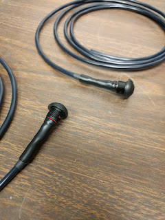
I took pictures as I soldered the wires to the switch. Deformity/dents on the heatshrink tubing on the last couple pictures is from trying to recover the unshrunk diameter of the tube since it shrunk while I was soldering.


Some closer shots. The LED polarity is marked on the plastic of the switch though the LED legs follow the usual "anode leg is longer than the cathode leg".
Obviously I shrunk the heatshrink around the soldered ends.

Both switches after shrinking.
I then covered the wires with larger heatshrink tubing to make it look a bit nicer (though it wouldn't be visible anyway).


Before and after.
I then utilised some larger heatshrink that had some adhesive on the inside to try to keep the stress away from the solder joints. I was lucky that the outside diameter of the tubing was less than the bushing. The adhesive heatshrink tubing took a lot longer to shrink since the wall was thicker and the adhesive also need to absorb the heat to activate.


Before and after. It didn't turn out entirely like I wanted it to, but it at least was adhered to the switch body.
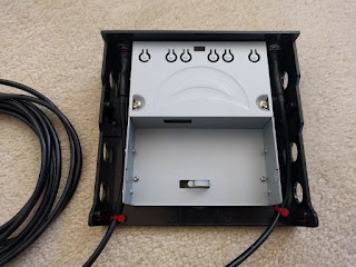
With that done, I needed to drill out the holes in the 3.5" to 5.25" external bay adapter for the switches. The week before I had observed how to utilise the vertical mill at work for basic usage, so I was relatively prepared the day after making the switches to drill the holes into the panel.
I had decided beforehand that I would utilise the vertical mill, since I would be able to keep the holes aligned horizontally even if I was off a bit vertically - I wanted this to look nice. I was also thinking to get a drawing out to have the machinist drill them out for me, but I didn't really want to deal with the awkwardness of asking him directly and/or asking the manager to have him do it.. Anyway, picture time.


Different views of the newly modified bracket.
I also drilled some small holes for securing the cable to the bracket to further remove stress from the solder joints as I had forgotten to mention before posting the pictures (which were done the day after). I next installed the switches and found why I was supposed to drill the holes larger, which is because of a boss of a different diameter that the O-ring fits around. Had I drilled it out to the proper size, the switches would be able to sit flat while compressing the rings, but that didn't happen and I didn't have access to anything larger than a 1/2" drill (I think the datasheet for the switch calls for a 13.6mm hole).
I decided to ignore it and keep working, since it wasn't entirely noticeable, and with the second switch, I tweaked the adhesive heatshrink too much and heard a snap. I think my heart stopped for a moment since I was hoping to hell that the snap wasn't from the LED legs. I took a moment with the semi-broken multimeter (the one seen in one of the pictures from the solder station project thing) to checked the forward voltage, which gave me a reading and drove the LED to light up enough to ease my fears; I also checked the switch, though I doubted the lugs would be able to snap like that - switch function passed. The snap was probably caused by the adhesive detaching from the switch body. I then secured the cables to the bracket once the nuts were tightened.


Front-ish and top view. Semi-broken multimeter in the background of the front view image.
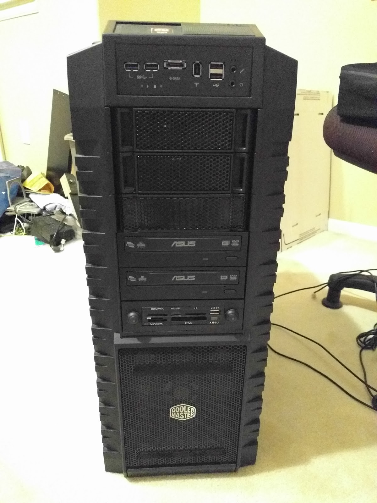
I then reattached the multi-card reader to the bracket before reinstalling it into Melty.


Same views as before with the card reader, and the assembly installed in Melty.
After spending a couple hours cable managing, I found that the Hirose connectors were not going to work with the Iwiss crimpers I currently had, and went with utilising a pair of needlenose pliers to do what I could to crimp them to the wire. After loading the plugs correctly, I shrank the heatshrink tubing before making the power harness. I decided to use red for the cable to the switch on the right side of the case, so that I would be able to differentiate between the cables if I ever wanted to change the button order.


The best-attempt crimp job, finished left switch harness, process of the right switch harness, and the power cable harness.
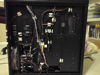
I then connected the power harness and then tucked the three cables awkwardly "in" the PSU shroud so that they would kinda stay put and not cause too much trouble.


New cable management, 5 volt power for switchbox added, inside shots, front shot (though probably not needed).
I tucked Melty back under the "desk" and hooked her back up before relaxing for the night and the next morning I began assembly on the board.


The usual pictures.
When it came time to the jacks, I soldered one of the three legs to the board and was going to utilise the PCI panel to line them up better when I found out that I screwed up the spacing between the jacks.

This actually isn't the correct panel (this one has 8 holes and not 9), but you can still tell that the spacing is wrong.
I was upset that had made that sort of mistake and decided to set it all aside and change gears to the solder station boards.
I forgot to mention that when I was drilling the holes for the bracket, I drilled out the holes in the correct PCI panel out larger so that the shoulder washers that I purchased would work with it and isolate the sleeve signals from one another. I also bead blasted it and painted it with some matte spray paint, but I never took pictures of it.
Anyway, I took the "wrong" panel to work to use the pin gauges to measure the diameter of the holes and it varied within a couple thousandths. I also measured between the diameters of the holes and also measured between the out-most two holes and divided by 8. I think it was when I was using the pin gauges when I realised the panel had 8 holes and not 9. The difference between measuring one and measuring the total and then dividing by 8 was one or two thousandths difference, so I think I took the result from dividing by 8 since that would be a bit more nominal than just taking the one measurement between two of the holes.
I decided to redraw the PCB instead of trying to fix the current one as I didn't want to have to deal with the existing polygons and traces. Surprisingly, it actually didn't take as long to redraw it, since some of the values would be staying the same between the new and old boards, and I sent the design to OSH Park once I was satisfied.


Before and after ratsnest tool.
I decided to bead blast the "wrong" panel during lunch to get the weird crud off the back (which was also present on the "correct" panel) and to make it a bit nicer. There's still some discolouration from where the crud was, and I'm guessing there was some sort of corrosion going on with its previous utility.


I just don't think my camera likes taking a good shot of the bead blasting.
I had found out that there were cheaper crimp tools to be able to crimp the tiny Hirose connectors, and after finding what it was and verifying in the list, I found it on Amazon and promptly ordered them.
I had booted Melty into Windows to check if I was having the same errors that a friend was having with a game and noticed that my files drive was offline, and after verifying it in Manjaro, I powered her down and investigated. Eventually I found a SATA cable unplugged from the motherboard and then I removed the one above it to plug the one that become unplugged back in (since I couldn't manipulate it back into the port with the one above it still plugged in) before plugging the one above it back in.
I then did a test tug and it became unplugged. I found that the release latch was designed just right so in a stacked configuration like that, the plug above it would depress it enough to where it wouldn't latch. I really didn't want to rerun the SATA cables (or even mess with any of the cables), and decided on trying to flatten the release latch so that it hopefully wouldn't do it again. After some careful squeezing with a pair of pliers, I got it flattened enough to where it stayed latched with the other SATA cable plugged in above it. The only thing is that it seemed like the release latch was dangerously close to the edge of the moulding that keeps it down.


Before and after.
While it wasn't directly related to the project, it was caused by this project. Anyway, the day after I crimped new connectors to the switch harnesses with the new crimp tool (Engineer Inc. PA-20), noticing that some of the previous contacts came off a bit too easily.

Just an after image because I was kinda in a hurry.
I had also really awkwardly used my new heatgun to shrink the new tubing, but it turned out well enough. The boards were supposed to arrive that day as well and I spent time desoldering all the components from the PCB, and once I was done with that, I just killed time in my room as I checked the tracking number.
Unfortunately, the boards never showed up, and for whatever reason, it took the package seven hours to get to the local post office from the main one which probably isn't more than an hour away. I was irate that the rest of my Saturday went to waste, but after getting home on Monday from work, I got the boards and quickly started on finishing the project.


The usual views. Yay 3.1! (Maybe "Yay!"...)
I first set the jacks into the PCB and checked the hole spacing to ensure myself that this wasn't going to all go horribly wrong at the last moment again, and i was definitely reassured.

Blast that bloody window!
I quickly began soldering the components back to the board, starting with the resistor, and I almost soldered the Molex header before the relays but I caught myself before I let too much solder flow.


Progress.

Being paranoid doesn't hurt sometimes, right?
With just one leg of the jack soldered, I tried a few things to try to keep the jacks aligned before deciding on just utilising "brute force". Once it was soldered, it looked fairly nice in the panel.


Still have a bit more to go.
Since there was the leftover PCB from when they were connected to the other PCBs in the panel at the board house, I decided to see if I could file it away enough so that it wouldn't interfere with the panel later on, and I was surprised with how easy it was - I just wished I thought about it before soldering the jacks on.

I think you can tell?
With how wide the outermost diameter of the shoulder washer is, I knew I had to cut them down so that they wouldn't overlap, and while I should've done it Saturday, I was a bit too frustrated with the post to do so. As I began cutting the first, I decided on a pattern, where the middle would be uncut, and the others would "D" outward from it.


The pattern as I was cutting the shoulder washers. The cuts shoulder washer, with the shoulder up.
Luckily it didn't take too long, and I awkwardly tightened the nuts with a pair of needlenose pliers (after failing to use a slotted screwdriver on one side of the nut). I tried to get the slots to line up, but eventually gave up.


Finger-tightened and plier-tightened.
Now that the board is assembled, it was time to install it. I first chose the slot directly above the Sound Blaster card, but found that I'd have no space at all for the plugs, so I moved it to the one above that. I also had a tight spacing issue with the 1394 front header plug, and so after I moved it up, that was no longer an issue.


Harnesses connected to the board, switchboard in the originally-intended location, switchboard in the revised location.
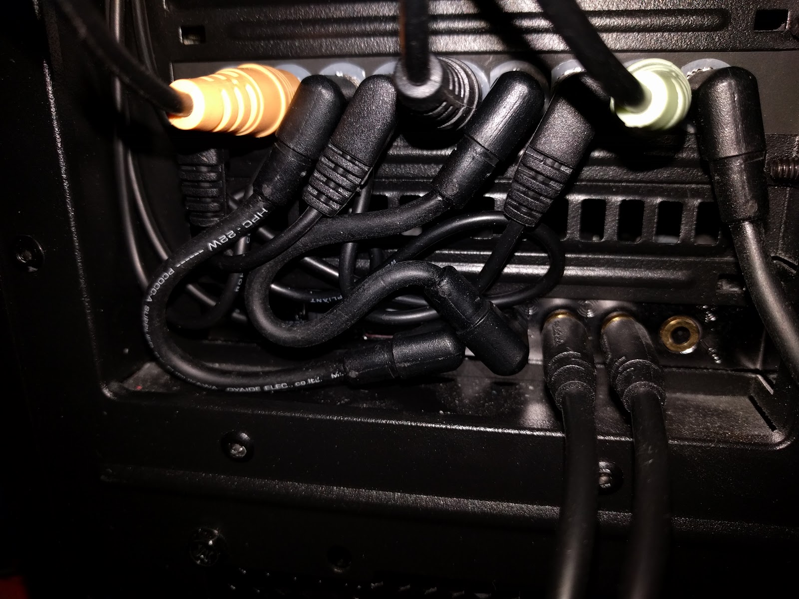
Next was to connect all the right-angle stereo plugs into their proper spots and to test out the sound. I ended up switching the spots for orange and black because of the Logitech's X540 cable harness. It obviously doesn't matter as long as the flanking cables are of the same "colour".


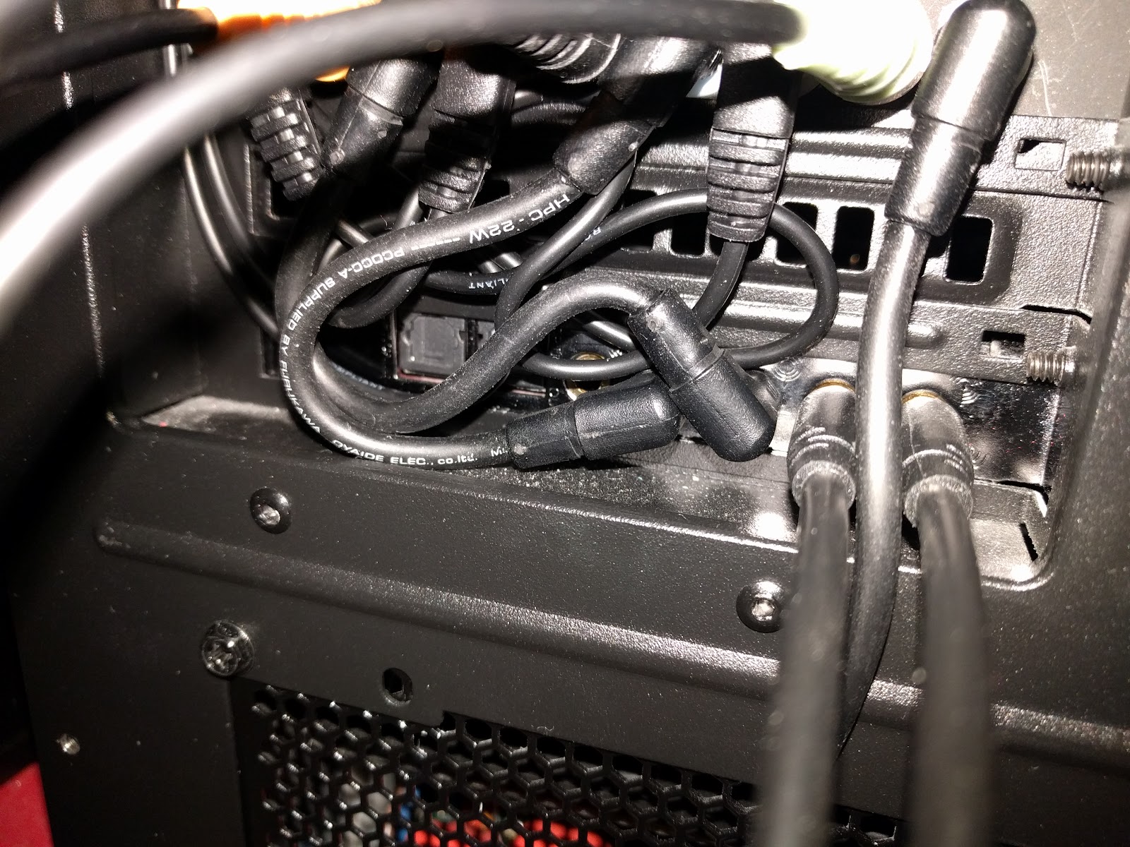

Views of the semi-organised "mess".
Manjaro passed the surround sound test, while I had a weird issue with Windows - the surround speakers were putting sound out through the center and sub while the centre and sub was coming through front speakers (or something like that). I checked that everything was correctly plugged in and such, and eventually looked up the manual to see that I had shifted plugs to the right by one jack when I had put Melty back under the "desk". After fixing the cables, Windows passed the surround sound test.


The semi-organised "mess", revised.
I think I explained that the LEDs in the switches would light for the soundcard not in use. So when the motherboard's soundcard is "active", the switch to change to the Sound Blaster card would be the lit LED, and vice versa. Probably a bit easier to see...


Sound Blaster card "active", motherboard soundcard "active".
I was done, I was satisfied, and I cleaned up whatever I needed to clean up and take care of other things before heading to bed.
Recently I found an Iwiss ratcheting crimper that works with JST connectors, which I think are very similar to the tiny Hirose connectors I use, and I had saved it in my wishlist while my compatibility question went unanswered on Amazon. Eventually I went ahead and ordered it to test it out for myself, since it seemed like I wasn't ever going to get an answer. I received it last week and first utilised it on the breadboard power cable, confirming my theory.
Today, I decided to redo the connectors (third time's a charm, eh?) since I was pulling out the bracket out to remount the card reader with washers, and ended up redoing 6 of the 8 connectors (two of them were crimped too well with the Engineer Inc. crimper and didn't want to come off at all). It was obviously a lot less awkward to redo the heatshrink now that the cable ends aren't inside Melty.


Four connectors after crimping new connectors, two connectors after crimping the new connectors (red and white), and completed ends. Also, dry skin is dry.
I also poked around and had a suspicion that some sheet metal screws from work (it comes with one of the parts that is purchased, but doesn't get used) was similar in diameter and thread to the ones that held the bracket to the case, and after confirming my suspicions, I decided to utilise them to secure the bracket to the case even further, although the screws are much longer than the ones that came with the bracket.


Longscrew is long (but doesn't encounter anything).
After getting the bracket back in Melty, I re-ran the cables and did a bit of cable management, closing her up once I was done (though I forgot to reconnect the USB 3.0 front panel to the header).


Inside views. I tied the cables from the card reader and a SATA power cable to the edge of the 3.5" drive bay (a bit hard to see minus the red cable ties).
I also meant to take a picture earlier of the cable management of the top fan cable, where I removed the pins from the housing and threaded it through the hole of the cable tie-down loop of the motherboard tray to get a much neater look.

Black (or red) heatshrink would make it look even better, but I realised too late. C'est la vie.
The relays are actually audible this time, since the board is attached to the panel via the audio jack threads. It's not a huge deal, since it's just one simple "click", though I doubt there's an easy way to silence the relays anyway.
The only way to improve this project is to have it auto-switch, but I think that requires parts I'm not familiar to using.
I think the main thing I learned with this project is to not assume. I only really took a ruler and thought that the hole spacing (centre to centre) is about 1mm without taking my calipers and measuring the actual spacing between the holes (by edge) and the diameter of the hole itself. Had I known I was going to screw up ahead of time, I probably would've made a proper 4-layer board with the sound traces in the inner layers, so that the ground planes would properly shield them from EMI. I suppose I could improve it that way, but I've already spent enough money on this project.
Eventually I'll work on the Raspberry Pi clock project, but it's just a side project and not a main project like this or the solder station. For now, I'll be able to focus on story-writing since I have about 3-4 stories I want to work on (one of them just needs another pass of proofreading), and sometimes I don't want to pull myself away from it to do other things.
Anyway, ciao for now!
Subscribe to:
Comments (Atom)