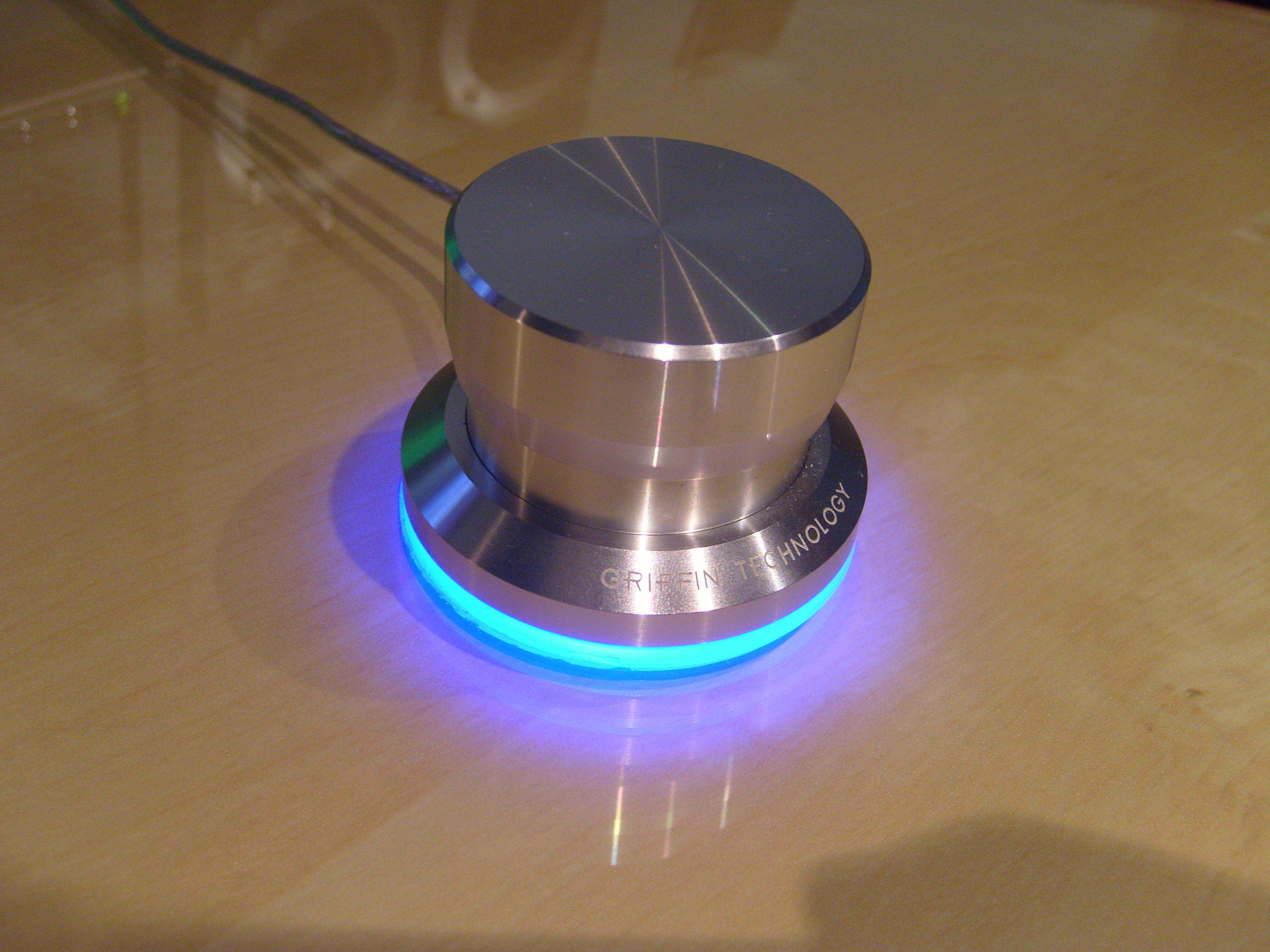
Griffin Powermate. (Image from Deskthority Wiki.)
A friend and I both have a Griffin Powermate that we bought around 2008, which we used for various things, and while it was great in Windows XP, it was pretty much non-functional in Windows 7. There were forums and such saying to use the Vista drivers and running the software in compatibility mode, but neither my friend nor I could get it to reliably work, and so we both stowed it away (or at least my friend did).
I think it was while I was poking around Adafruit or something when I encountered the
rotaryio library or the rotary encoder guide, but regardless, it got me thinking about the Powermate. It's a bit hard to remember this initial stuff, since I was also kinda deep diving with MCUs and CircuitPython, as well as working on the 3DS input redirect controller and some other MCU projects.Anyway, the first thing was trying to figure out how to get the thing apart without doing too much damage or creating more work later, and I asked my friend if they still had theirs, to which they replied that they did. I wanted an extra as sort of a "sacrificial lamb" in case worst comes to worst, though I did also have a link saved to an ebay listing for buying one. One of the images on the ebay listing shows the top cap popped off, and when I was able to try it out on mine, I was stupified on how easy the cap was to take off, but to be fair, I never had a reason to pull the cap off or even try it (and neither did my friend). Below the cap on the main body is a little felt piece that I kinda ignored because I saw a nut that was holding the rotary encoder to the main body, but unfastening the nut didn't yield any meaningful results. Because there is a sort of gap between the bottom and top pieces (you can see this in the above image, especially at full-size), it was more likely that the body is made from two pieces of machined aluminium that were assembled in some way (either by press-fit or some sort of threading).
When I got my friend's Powermate, I first tried to twist the two parts apart, but I couldn't find channel-lock pliers that were large enough for the base (nor did I want to buy one large enough for doing so), and I wanted to avoid the pipe wrenches at work because of the lack of curve in their jaws. I also tried a trigger clamp, but it ended up slipping from the lack of surface area. Looking at the bottom at the glue that attaches the plastic to the metal, I found a somewhat large spot that the glue didn't spread to (the glue is white btw), so I decided to use the Jimmy pry tool (iFixit) to see if I could pop the bottom off, and well, it was quite easy. I unfastened the nut and went to to desolder the USB wires from the board, which gave me a better look inside, and I saw a more obvious seam between the parts on the inside. I think I tried the pointy side of the metal spudger (again, iFixit) between the moulded strain relief for the USB cable and the bottom part of the body, and it did slowly give, but because of the strain relief compressing, it made it tough to free the bottom piece. I think if I had two metal spudgers, it would make it easier to separate the parts, but I still got it apart with just one. I felt a little stupid for not trying that before popping the plastic piece off of the metal, but it wouldn't be too hard to glue it back on.
With the new separation strategy, I applied it on mine to be able to get the board from mine, and because I was already at the soldering station, I went and desoldered the rotary encoder from the board, which was easier said than done with a small cone tip (I should've used the larger cone tip for more thermal mass). With the board and rotary encoder, I went to pull measurements for the footprint I would need, and it was a little tough since I damaged some of the vias and ripped off one of the retention pads. Measuring the vias was a little tough, even with pin gauges, but I think I ended up with something that worked, and even getting the placement of the rotary encoder footprint position on the board was also a bit tough since the board has what someone calls "mouse bites" at the north, south, east, and west locations (which can be seen in the larger versions of the board images below).


Bottom of the board, top of the board, body bottom (with marring from the metal spudger).
The board was fairly easy to design, since I was using an ATSAMD21E18A-A, which fit in between the button and encoder legs of the rotary encoder, and I had to put a reminder in my notes that I would need special pads for connecting the programmer to the board and that I would need to figure something out for the reset button. For the lighting, I went with sixteen RGB LEDs (specifically, WS2812B-2020 aka NeoPixel Nano 2020 from Adafruit), and this was because it seemed to be a good density, along with the fact that I already had the placement equations from a test board for another project (extended 10-key, more on it in another post). (I think I already said it last post, but I was working on a lot of these CircuitPython/MCU project in a short amount of time and/or concurrently.) Anyway, I had a realisation moment that I could also do twelve LEDs instead and made a copy of the board to reduce the LED count and reposition them accordingly. I think part of this is because of the theoretical current draw, which is theoretically 12mA per colour (according to the datasheet), and translates to 36mA per LED at full-brightness white. With 16 LEDs, the theoretical current draw is 576mA, and 12 LEDs drops it to 432mA. I was trying to keep the current draw under 500mA, which is the USB 2.0 spec, so I decided I'd order both versions of the board and do some testing to see if there was going to be a problem, since I have a charger that outputs 5 volts at 500mA.


The board designs for sixteen and twelve LEDs.
I ordered the board and parts for the board with other boards and parts for those other boards, and when I had everything, I soldered the LEDs first because of their moisture senitivity level of 5A (I have 24 hours to mount the device or place them into correct storage after opening the bag). Though I did solder one just fine by eye, it was a lot easier and a bit cleaner with magnification. Also, I did use the bench grinder at work to get rid of the breakpoints on the board (aka "mouse bite
The next thing was to create some animations and such for testing because I wasn't sure if my friend would want 12 or 16 LEDs, and I still had the test wires soldered to the boards, so I'd be able to just run the wires out of the USB hole in the body while having the body pieces stacked so it would be assembled enough to not let light leak. I ended up using the loose rotary encoder (I hadn't desoldered the rotary encoder from my friend's board yet) to help keep the board in position with the loose assembly, and it was kinda hard for me to tell the difference between the 12 and 16 LED versions, even with the "chase" animation that looked pretty bad because of the light bleedign to the opposite side. I kinda wished I had another dev board to be able to test side by side, but I made do with what I had. Kinda poking around, I was wanting to see the brightness difference between the single LED on the original board and the 16 LEDs on my board, and though the original LED wouldn't come back on after resoldering the USB, I found that the LED was powered by 5 volts with a bit of probing. I tried to take a picture, but it kinda tones down how crazy difference in brightness.

Left is old LED, right is new LEDs. Seriously, I really did feel like I created a monster.
You can tell with the cap on the left one that these are loosely put together.
You can tell with the cap on the left one that these are loosely put together.
It kinda took a while before I was able to head over to my friend's place, but I did show it off to get a decision, which ended up being the one with 12 LEDs for less brightness (even though the brightness is controllable, but whatever). With what was goign to be used decided (I ended up taking the 16-LED board), I desoldered the wires from the board and soldered everything else on (even the capacitors on the opposite side of the board from the USB holes, even though it was proven to be fine without them).

The boards mostly ready for programming.
For the bottom pieces of the body for my friend's Powermate, I found the white glue stuff scraped off pretty easily, so it wasn't too bad to remove, and I was at first thinking of using superglue, but then I remembered I had some clear jeweller's glue stuff (B-7000, but mine might be a knockoff?) that might be a little better because it's not super thin. Before I put the glue on, I went and got a couple trigger clamps to be ready to clamp the pieces after gluing as well as keep them clamped together as it cures for 48 hours. I had to remove the excess glue after curing from the inside and outside, and the latter was easier to do than the former. Because of the clamping and such, there's 100% coverage of glue between the plastic and the metal, unlike whatever Griffin used, and it's also clear (which doesn't make any difference).
I think I was waiting on building the bootloader and CircuitPython because I would need to clone Adafruit's Git repositories to be able to do so and based on some experience with Git repositories, it can take a while if there's a large history/archive or whatnot. After finally taking the time to try it, it didn't seem to take too long until
git submodule sync or git submodule update (I don't remember which), but after it finished, I was able to make the necessary folders (one in the bootloader repo and one in the CircuitPython repo) and get all the copied config files changed accordingly. Building was easy and quick (I probably didn't need to add -j32 to the build command, but I did anyway), and CircuitPython and the bootloader were ready. Soldering the USB cable on and soldering the programming wires to the pads were the only thing left for the board to be ready for the programmer, and I followed the CLI instructions because it should work and I wanted to avoid having to use Windows in some way (Adafruit's guide on programming the bootloader uses Windows). Anyway, it worked just fine and the "boot" drive showed up after the MCU rebooted, which meant that it should be working fine and I could install CircuitPython by dropping the firmware file onto the "boot" drive. After the MCU rebooted again, the CIRCUITPY drive showed up instead, which meant that CircuitPython is running, and poking into the serial console allowed me to just run some test commands. I think I was a little weirded out when I saw that CircuitPython was an alpha of version 7, but I thought it should be fine, since everything should run fine. Nope. It gave me a version error for the libraries, and trying the correct version of the libraries still gave me the same error. I went back to the CircuitPython building guide and read over the part that I skipped over, which told me how to switch the version of CircuitPython before building (remember, RTFM means to read everything and not just the parts you think are applicable), and after building CircuitPython 6.2.0, I went to install it on the MCU (the board is still hangin' out) after getting back to the "boot" drive (double-clicking the reset button). With the stable version of CircuitPython running, I was able to confirm operation (I think I was still using the LED test script that had the animations), and the board was ready for the rotary encoder and final assembly.
Friend's board ready for final assembly. (Something that was stored with their Powermate screwed with the clear cable, so disregard the yellowed/blackened spots.)
I think I was going to use the trigger clamps again to press the two body pieces together, but I ended up not needing to do that because I was able to do it entirely by hand? Which would make sense, since it's cheaper to make it so that humans can press the pieces together for less labour/tool costs. Regardless, I don't remember that well. Anyway, the renewed Powermate was ready for getting the final script together and tested.

Friend's Powermate after assembly.
Because the Powermate supported five input types (pressing the button, clockwise turn, anticlockwise turn, holding the button while turning clockwise, and holding the button while turning anticlockwise), I wanted to keep that same funcitonality intact and had an idea of how to do it, but was waiting to be able to test it because I didn't want to use the same awkward setup I used for tinkering with
rotaryio and the rotary encoder. The idea I had did work, it's just that the timing needed a bit of tweaking. Originally, the Powermate had a companion software to translate the inputs into actions based on the active programme, but I believe that was part of its downfall past Windows XP (Vista doesn't count because hardly anyone used it). Anyway, replicating the software is easier said than done, and was not something I was wanting to do. I wanted to keep it literally plug and play: no software to configure, no drivers to install, etc. To have separate "profiles" within the Powermate, I created a framework that would have seven profiles (could be expandable if desired), and each would have their own colour (yay RGB). I used the "holding the button down while turning" for changing profiles, so when holding the button down, the current profile colour would come up and turning clockwise or anticlockwise would change the colour and the profile. Though this reduces the functions from 5 to 3, with the profiles, it expands it to n×3 (where n is the number of profiles), and so 21 functions total in the case of the framework.
Profile changing demo. Colours are really washed, but the order is red, orange, yellow, green, cyan, blue, magenta.
Unfortunately my friend wasn't very responsive of what they wanted their Powermate to do, and I just threw the suggestions I gave into the code and called it a day. Was a little annoying that I made the framework for nothing, but oh well. For mine, I have the button trigger play/pause because the only dedicated media buttons I have for Pod is the ones on the speaker remote, which doesn't work if the speaker went to sleep; turning just turns the LED on or off (in a sort of pinkish colour); and I just left the framework for hold and turn because I really didn't know what else to do with it. I could've used it as a volume adjustment, but whenever I actually adjust the volume, it's usually only by one step of 5% and the adjustment is tied to the speakers because I have the speakers connected via USB (the speakers don't seem to like anything less than 3% volume increments).
I recently found a debouncing library, and might play with it for the button, but because my friend's button only turns the LED on and off, I'm not worried about it. Also CircuitPython 7 will introduce ways to hide the
CIRCUITPY drive and such, but well, it's easier said than done to get the "boot" drive to show up since there's no way to press the reset button without disassembling the Powermate. I kinda wanted to sandblast the Powermate to get rid of Griffin's markings, but I ended up leaving it alone because I wasn't really wanting to separate the metal from the plastic, mask the plastic off, or sandblast the plastic with the metal. I was kinda awestruck for a while when I got it working (probably after loading CircuitPython 6.2.0) since it was a bit hard to believe that I got my first finished MCU project up and running with no problems. Though I'm not fully utilising it, it still was a worthwhile project to turn something hardly usable into something usable.