I forgot when I saw an article about it, but it was pretty recent, as Kaisen 2.0 was released 14 December. I meant to get it and see what was different, but kept forgetting.
Anyway, I tried to read through the changelog, but it ended up becoming a chore, and I decided to try to search for whisker for the hell of it, expecting no mention. But I was very wrong once I typed s into the search. Had I tried to hold out a little longer, I would've read the line that says Whisker is now the default menu, but no, because ADHD. I doubt my previous post into the void was the cause, but I'm sure someone(s) somewhere either said something on the forums, gitlab, whatever. I was so excited that I had to post about it.
I don't remember if there was a system recovery version of Kaisen, but there is now, which is a lot more of what I want, since my use case is more towards that than having something that I could install and daily drive (Manjaro's still working just fine for me).
17 December 2021
21 September 2021
Ventoy, Kaisen Linux, Clear Linux
I found Kaisen Linux a while ago, but didn't really get around to testing it until early August (I had to download the newer version).
I couldn't remember what USB multi-boot utility I was using after
Back to Kaisen, it's a distro with sysadmin tools, which what originally got me interested in it because I wanted something that was more current and free than Parted Magic (last I remember, Parted Magic made you pay for current versions, but had previous versions for free), and also something less annoying than GParted Live (GParted asks for the keyboard layout during bootup). While Kaisen doesn't boot as fast as Parted Magic or GParted from what I remember, it's something I like more, even though the XFCE menu is the stock one and not the superior Whisker menu. The ISO includes English and French as an option, like Parted Magic does, but the keyboard is QWERTY instead of AZERTY when booting into English (another annoyance with Parted Magic). The menu is categorised appropriately, I think, but for someone like me that's used to the Whisker menu, it was annoying to find
With the power of Ventoy, I wanted to rebuild a set of Linux distros as I previously had on the drive (installing Ventoy wipes the drive), so I poked around to see what else to get besides some obvious choices like Manjaro, openSUSE, and Fedora. I came upon Clear Linux, which is it's own distribution (not forked from anything), and decided to give it a shot since it claims to be optimised for performance. I don't think I've ever booted any faster into a live distro than Clear. I tried to test on Triela, but Clear requires certain CPU instruction sets to run, none of which Triela has (SSSE3 (three Ss, not two), SSE4.1, SSE4.2, CLMUL). Because Melty has those instruction sets (pretty much AMD FX CPUs and newer), I could've tried Clear on Melty, but I didn't really feel like bothering with it. Not really much else to say, since I didn't really do much besides poke a bit at it.
I did try Debian, but I think I had problems or something, but well, I really prefer something that has newer packages like openSUSE Leap. I get that Debian's supposed to be rock solid, but honestly, Manjaro's been pretty solid on Pod for only having installed once. I also tried GhostBSD, but I don't remember if it worked; if it did, I wasn't in it for too long (I was really just after if I could boot into it or not with Triela and Bazett). Oh, one interesting thing when booting into openSUSE Tumbleweed on Bazett was that during the boot, it showed the HP logo.

The logo section was blank when I booted openSUSE Leap on Triela, but it's possible she's too old for that sort of special treatment (or it could just be only on HP laptops, I dunno, I'd need a larger sample size).
I couldn't remember what USB multi-boot utility I was using after
multiboot, but I couldn't seem to find it? Or it may just have been multiboot, but regardless, I couldn't find any hint of what it was. I came upon Ventoy, which is kinda multiboot's successor. Anyway, you install it to the USB drive and then drop the ISOs (or IMGs) directly onto the USB drive. I didn't really read the doc that well since I only read it for installation of Ventoy on the USB drive and then closed the tab, so I didn't realise I just had to plop the ISOs to the drive. It's a lot easier/faster/nicer than multiboot since it's drag and drop after the initial installation (multiboot has an install/uninstall ISO process that unpacks/cleans them in a certain way, which takes longer than just dropping/deleting an ISO file). IMGs only really work on UEFI systems btw, I learned this with Memtest86 V4 and Triela.Back to Kaisen, it's a distro with sysadmin tools, which what originally got me interested in it because I wanted something that was more current and free than Parted Magic (last I remember, Parted Magic made you pay for current versions, but had previous versions for free), and also something less annoying than GParted Live (GParted asks for the keyboard layout during bootup). While Kaisen doesn't boot as fast as Parted Magic or GParted from what I remember, it's something I like more, even though the XFCE menu is the stock one and not the superior Whisker menu. The ISO includes English and French as an option, like Parted Magic does, but the keyboard is QWERTY instead of AZERTY when booting into English (another annoyance with Parted Magic). The menu is categorised appropriately, I think, but for someone like me that's used to the Whisker menu, it was annoying to find
gparted. While I did find it, it's sadly quicker to just Alt+F2 and type for it. I don't think the Whisker menu is customisable like the stock XFCE one, but Whisker does include a search function that makes it easier to find stuff. It'd be nice if the Kaisen team can use Whisker instead or alongside the stock one, but I doubt it'll happen. But with this, definitely not bothering with Parted Magic or GParted Live ever again.With the power of Ventoy, I wanted to rebuild a set of Linux distros as I previously had on the drive (installing Ventoy wipes the drive), so I poked around to see what else to get besides some obvious choices like Manjaro, openSUSE, and Fedora. I came upon Clear Linux, which is it's own distribution (not forked from anything), and decided to give it a shot since it claims to be optimised for performance. I don't think I've ever booted any faster into a live distro than Clear. I tried to test on Triela, but Clear requires certain CPU instruction sets to run, none of which Triela has (SSSE3 (three Ss, not two), SSE4.1, SSE4.2, CLMUL). Because Melty has those instruction sets (pretty much AMD FX CPUs and newer), I could've tried Clear on Melty, but I didn't really feel like bothering with it. Not really much else to say, since I didn't really do much besides poke a bit at it.
I did try Debian, but I think I had problems or something, but well, I really prefer something that has newer packages like openSUSE Leap. I get that Debian's supposed to be rock solid, but honestly, Manjaro's been pretty solid on Pod for only having installed once. I also tried GhostBSD, but I don't remember if it worked; if it did, I wasn't in it for too long (I was really just after if I could boot into it or not with Triela and Bazett). Oh, one interesting thing when booting into openSUSE Tumbleweed on Bazett was that during the boot, it showed the HP logo.

Not the best shot, but I was trying to avoid reflections of myself and the overhead light.
∞ Tumbleweed is right below the shadow of my phone and above the bright spot of the overhead light.
∞ Tumbleweed is right below the shadow of my phone and above the bright spot of the overhead light.
The logo section was blank when I booted openSUSE Leap on Triela, but it's possible she's too old for that sort of special treatment (or it could just be only on HP laptops, I dunno, I'd need a larger sample size).
09 September 2021
Minor-ish Site Update
Decided to make text in the HTML code tag easier to read by increasing the font size a smidge and adding a grey background because it was getting annoying for me to try to read when proofreading posts. A late change, but at least a welcome one. (Also I forgot how I usually do these and couldn't easily find a previous one, so it's like this this time. Yay 2.2.0!)
8-Bit Character LCD/Character LCD Clock Update
In the Character LCD Clock post I mentioned wanting to test out 8-bit communication and having to write my own library for it, and I recently remembered about it to stick it in my projects folder.
I ended up grabbing the datasheet for the 20×4 display that I have and Adafruit's
In the write function, it normally sets the "top" four bits to be written on the pins set to
I used
And because of this, I decided to make the Character LCD Clock have an 8-bit connection just to use up some more pins and not let my library modding go to waste (well, it's not that hard of a mod, but still...).
I ended up grabbing the datasheet for the 20×4 display that I have and Adafruit's
character_lcd.py source code for references, but when I really started looking at both of them (and playing with some things in a Python shell), I found I didn't need to write my own library and could just modify Adafruit's code. As for what I modified, I changed _LCD_4BITMODE = const(0x00) to _LCD_4BITMODE = const(0x10) to set it to 8-bit mode from 4-bit. Yes the variable name didn't get changed, but it means that there is minimal change to the code. The other thing I changed was the __init__( arguments for the additional data pins, the class variables that are made from those arguments, the write function (specifics soon), and the __init__( arguments for Character_LCD_Mono and Character_LCD_RGB.In the write function, it normally sets the "top" four bits to be written on the pins set to
self.dl4 through self.dl7, sends a three-part pulse (self._pulse_enable() function), then sets the "bottom" four bits on the same four pins before another pulse. For 8-bit, all eight pins need to be set, and I just brought up the lines for the "bottom" four bits above the lines for the "top" four bits and then changed the class variables to match the ones I added before. The pulse only needs to be sent once after the eight pins are set.Character_LCD_Mono and Character_LCD_RGB have the __init__( arguments change since they pass the pins over to the parent class (the 20×4 display I have does have a backlight).I used
mpy-cross to turn it into a smaller .mpy file and tried it out. I ended up making it the wrong version because I never recompiled mpy-cross after setting the CircuitPython version to compile when I was compiling CircuitPython. Anyway, after that, the 8-bit library worked just fine, and I thought it seems faster, but I think it's just a placebo. The reason is that the pulse function has three 1-microsecond pauses and the only other limiting factor is the 1-millisecond pause in the write function before it sets all the pins; therefore with 4-bit, 1006 microseconds is spent to write one character, and 1003 microseconds for 8-bit. It's very negligible, and I can understand why Adafruit never bothered with making an 8-bit library or why 4-bit is so much more common, it's because the benefit for eating up four more pins is not worthwhile in any meaningful way. However, 8-bit makes sense when it's a small project that doesn't use all that many pins, which means it's just to connect the pins to something rather than nothing.And because of this, I decided to make the Character LCD Clock have an 8-bit connection just to use up some more pins and not let my library modding go to waste (well, it's not that hard of a mod, but still...).
12 July 2021
User-Made Python Modules
In the Qt5 post, I mentioned that I should break my 4000+ line programme down into modules, and near the start of this month, I decided to try it out with a different programme that is much smaller and simpler. Because the large programme has about 38 classes, I was going to want a separate folder called
Anyway, I did end up finding what I wanted, but I wish it had more graphics instead of a bunch of text and examples to follow along with. I found from there that it was just
Changing the large programme was fairly easy, because I just had to replace
I'll now go over some of the things that might be useful for anyone looking for the information. First, let's start with a file tree that will be used as reference.
Things to know:
I think that's everything, since I have nothing else in my notes.
lib within the folder that the main script is in, but I was needing to know how to import from it. I searched around for a while, but wasn't finding anything useful, and though I found something, the answer says:Note that injecting directories intoI think the reasoning behind avoiding adding paths tosys.pathis not the usual way to set up Python to search for modules. Usually it is preferable to add/home/jake/Documentsto your PYTHONPATH environment variable.
sys.path is because it might not work across different computers (not "portable"). CircuitPython MCUs with modules on SD cards require /sd/ to be added to sys.path because there is no other option (that I know of).Anyway, I did end up finding what I wanted, but I wish it had more graphics instead of a bunch of text and examples to follow along with. I found from there that it was just
import folder.module, so I went to try it out with the simpler programme and it worked with no other changes besides the import. I went to copying portions of the large programme to make a much smaller testbed, and started off with the common functions, which was aptly named common.py. There were some changes I did need to make, one of which was to move the global variable regex into its own class and function to return the regular expression used for input validation. Another was to move the setting clipboard text function from the main window to its own class and function, another was to write/get the required precision to a file because there wouldn't be an easy way to be able to get it from the combo box of the main window, and the last major one was to move the message box function from the main window. I tested a couple simple classes and made adjustments as necessary when Python gave me errors, and eventually played around with stuff in common.py a bit. I found out that I could just have a function for regex, setting clipboard text, and messagebox, so I made the according changes and it worked just fine.Changing the large programme was fairly easy, because I just had to replace
regex with regex() and window.to_clip( to to_clip( before I even started modulisation of any of the 37 calculation classes, and the modulisation just required me to import the usual PyQt5 classes, common.py, changing the working directory when necessary (for reference images), and importing the module in the main script. I also made some quality-of-life improvements to the main script as well (now that it's a few hundred lines instead of a few thousand), and also took the time to insert a "clear/reset calculator" function to each of the modules instead of relying on old code that doesn't always work or causes the programme to crash. Anyway, it's much more manageable, and there's not a whole lot else to really say.I'll now go over some of the things that might be useful for anyone looking for the information. First, let's start with a file tree that will be used as reference.
Example filetree:
- project/
- main.py
- modules/
- module1.py
- module2.py
- sub_modules/
- sub_module1.py
- sub_module2.py
Things to know:
- The
modules/folder must be in the same place asmain.py(withinproject/in this case). - The structure used for import is
modules.module1formodules/module1.py, andmodules.sub_modules.sub_module1.pyformodules/sub_modules/sub_module1.py. - If
main.pyimportsmodule2.py, which needs to importmodule1.py, thenmodule2.pywould still usemodules.module1for importing becausemain.pyserves as the basis for the location. - Modules can contain (class-less) functions and classes.
- Use
from modules.module1 import *instead ofimport modules.module1if you'd like to use function or class names as-is (function()instead ofmodules.module1.function()). (Probably obvious if you've used Python enough.)
I think that's everything, since I have nothing else in my notes.
09 July 2021
Parts Inventory, and Digi-Key and Mouser Data Matrix Barcodes
The first step was to get a barcode scanner that also reads 2D barcodes and is reasonably-priced, and SparkFun's 2D Barcode Scanner Breakout was the answer. When I found it, I thought their stock of 42 would be okay, but when I looked at it the next day, they were all gone! I think I sat for a few days before I found that SparkFun does have a "wait for backorder items before shipping" option, so I went ahead and put in an order, since they said they had about 144 units being made. I technically would've been fine with the module itself, but I don't know if they'll ever be bringing them back in stock, since it's part of their "SparkX" line which is for experimental stuff. Looking through their blog yesterday, I guess the scanner breakout was released 28 May, so maybe because it's such a new product, they're focusing all the modules to the breakout boards until demand goes down. Hell, even as I write this, they're out of stock once again and planning on making 60 more; the "Top Sellers" tab on their front page contains the scanner breakout, and for a good reason.
I got the scanner a couple days ago and played around with it some... I mean I was seriously like this:

And it was great being able to scan something that would be automatically entered in a spreadsheet, text editor, whatever. While the barcode scanner app for Android by ZXing Team is a long-time favourite of mine, it's not a very streamlined approach when I need to get the scanned data to my computer (I have it set to auto-copy the scanned contents to the clipboard, and then I paste it into Discord).
Digi-Key's labels for each bag of parts contains a Data Matrix code (at least the newer ones do, I don't know when they switched over, but I have some Digi-Key bags at work that were from 2015 that has a 1D barcode), and scanning that with the barcode scanner (the one from SparkFun) yielded info similar to this:
[)>06P559-1099-ND1PPS2801A-4-AK1K7013275410K8165562911K14LJPQ1311ZPICK12Z956474013Z5583520Z00000000000000000000000000000000000000000000000000000000000000000000000000000000000000000000000000000000000000000000000000000000000000000000000000000000000000000000000000000000000000Which I could kinda figure out stuff from, but I needed more info. I did a quick search and found some people trying to figure it out (this being one), but no one had a complete list, so I decided to just figure it out myself. At work, I scanned one with the app and found some non-printing characters as "tofu" and it made a lot more sense to me.

♫A little bit of tofu in the text.♫
Using Discord, I pasted it within a code box so that I don't lose the tofu, and though they don't show, they were still there when I transferred it into Mousepad.

Tofu, demystified.
I use CudaText as my main text editor, but well, the non-printing characters are less obvious. Anyway, Unicode 001d is "Information Separator Three" or "[GS]" (Group Separator), and 001e is "Information Separator Two" or "[RS]" (Record Separator). I didn't really care what they were besides that they were non-printing control characters, but well, the difference between 001d and 001e would kinda serve me later. Looking at the data in Mousepad with the boxed control characters, It was much easier to make things out, and I was able to figure out that the "category" markers precede whatever number they are. I think it'll just be easier to share the findings first before I talk about certain items individually.
Digi-Key barcode data (using data from Mousepad screenshot):I had thought 11K might've been MSL, but nope, the NeoPixels have the same value of 1. The invoice number (10K) stumped me for a little, until I went to check an email that I probably still had, and sure enough, the numbers matched. Since I don't need purchase order numbers for my personal orders, work was the best bet for figuring out K, though before scanning the two samples at work, I wasn't entirely sure how the data was structured.
- [)>
- Probably a scanning software thing.
- 06
- Probably another scanning software thing, this number is the same between Digi-Key and Mouser.
- P559-1099-ND
- Part number, either customer-specified or retailer-specified, prefixed with P.
- 1PPS2801A-4-A
- Manufacturer part number, prefixed with 1P.
- K9438
- Customer purchase order (PO) number, prefixed with K, may be blank.
- 1K70132754
- Sales order (SO) number, prefixed with 1K.
- 10K81655629
- Invoice number, prefixed with 10K.
- 11K1
- No idea what this is, but seems to always be 1, prefixed with 11K.
- 4LJP
- Country of origin, prefixed with 4L, uses ISO 3166-1 alpha-2 codes.
- Q13
- Quantity of items, prefixed with Q.
- 11ZPICK
- No idea what this is, but seems to always be PICK, prefixed with 11Z.
- 12Z9564740
- Part ID, prefixed with 12Z.
- 13Z55835
- Load ID, prefixed with 13Z.
- 20Z00000000000000000000000000000000000000000000000000000000000000000000000000000000000000000000000000000000000000000000000000000000000000000000000000000000000000000000000000000000000000
- Probably some sort of filler, prefixed with 20Z
While at work, I decided to scan Mouser's to see what it contained, and it was much less. Let's start with a screenshot of the data, and then jump right into the breakdown.

Miniscule compared to Digi-Key.
Mouser barcode data:I wasn't paying too much attention yesterday, so I thought Digi-Key and Mouser use the same structure, but I guess not. It's possible 11K for Digi-Key might be an another invoice number field, but I can't say for sure, and it's something I don't care about in all honesty. I was double-checking 11K for Mouser with some other part and found 1V, which might be something new, but again, not worthwhile for me. At the least, hopefully people looking for the structure find this blog post and is helpful to them.
- >[)>06
- Probably scanning software stuff. There's no 001e control character before 06, but at the least, the 06 is still the same in comparison to Digi-Key.
- K9439
- Customer purchase order (PO) number, prefixed with K, web order number is used if customer does not provide a PO number.
- 14K022
- Line item number (the line the item appears on an invoice, packing list, etc.), prefixed with 14K.
- PTP0194
- Customer-specified part number, prefixed with P.
- 1P02-09-1117 (Cut Strip)
- Manufacturer part number, prefixed with 1P, appears instead if there is no customer-specified part number. (This is from something else and isn't in/from the image.)
- Q10
- Quantity of items, prefixed with Q.
- 11K062059574
- Invoice number, prefixed with 11K.
- 4LLI
- Country of origin, prefixed with 4L, uses ISO 3166-1 alpha-2 codes.
- 1VNeutrik
- Manufacturer name, prefixed with 1V, may not be present.
Moving on. Because I found out about the control characters, I needed to figure out a way for the barcode scanner to send them. I tried the "serial over USB" (USB-COM) mode of the barcode scanner and ended up in an empty
screen when loading up /dev/ttyACM1 (/dev/ttyACM0 is my Powermate), so I had to go the serial over UART route with a dev board. I used the Trinket M0 because it's small, and hooking up the barcode scanner to it was easy after I got a 6-position header soldered to the barcode scanner. I then pulled up a UART serial Adafruit guide as reference and had to try to fill in the blanks myself. It didn't seem to print anything out properly, and I tried baud rates of 9600 and 115200 in the code which both were claimed as the default in the settings manual (9600 is listed first as the default, but then 115200 is listed as the default three times after that, but eventually, I decided to scan the 115200 baud rate setting. And that was the problem all along, some mysterious default baud rate setting (I had a thought to go through them individually, but I didn't feel like it). I also tried USB-COM mode again and scanned the 115200 baud rate setting, but no dice, so I gave that mode up entirely.A new problem arose, the printed text still contained no control characters, but the code I used has a line for printing the raw data, and after commenting that out, huzzah! I forgot when I swapped my janky wire set up for the 20-position GPIO set I bought along with the barcode scanner, but I did so because the ground wire kept popping off the barcode scanner header, and honestly, I should've done it sooner since it had a much better hold on the header pins. Anyway, the next issue was the fact that the raw data is a bytearray, and I needed to convert it to a string. Well, I thought I did, but I eventually realised that the conversion in the code was actually keeping the control characters, and that
print() was the culprit of not printing them (I mean, they're called "non-printing" characters for a reason). While trying to see if print() had some sort of option to maybe print the characters, my eyes glanced over "sep" and I was reminded of replace(). Huge duh moment. I used a tab character to replace 001d and had replace() replace 001e with nothing, this would make things much more printable.It was kinda in that mess where I was also thinking of trying to write the raw data to a file, and because I normally use
open() in text, it took me a moment to remember about its ability to write bytes. While it did work with normal Python, CircuitPython refused to do it in the test because the flash appeared as read-only to it, and though I would've used an SD card over SPI, I didn't want to make things harder than it should be (plus I had just ordered the micro SD card breakout from Adafruit, so I would've had to wait anyway). Anyway, I think it was after I got replace() into the code (or it might've been a little before?) was when I decided to use the USB-HID library to emulate a keyboard, and because there's a library that allows a string as the input of what to send to the computer, I wanted to utilise that. The problem is that the examples changed with the documentation, so I had to try to figure it out, which wasn't too hard, but I was able to get it to work. It doesn't type nearly as fast as the barcode scanner directly, but at least I can get the control characters for processing before sending to the computer.Because the
.read() command for the UART serial only lasts for a bit, it was hard to test in the CircuitPython console, but it was fine in the code because of the looping. I also tried to send commands to the barcode scanner, but it was difficult at first because I forgot that there was a command prefix it looks for (^_^, caret underscore caret, I'm not kidding), and when I got it in there, it worked as intended. There was some other things I did/tried, but I won't talk about it because it's not really worthwhile.
The output (or at least simulated) from the MCU. I forgot the newline, but oh well.
Though I could do all the processing on the MCU of the stuff I care about (manufacturer's part number mainly), I wanted to keep the processing that needs to be done on the MCU as minimal as possible to make the job of scanning the inventory as quick as possible. I also added line in the code to send the save hotkey after it "types" the data, so that it's as automated as it can get. I still need to write the code for processing the file down to part numbers, but that won't be too hard and Pod will have it done before the snap of a finger.
Originally, I was thinking of buying a second barcode scanner (before I even bought the first) for a "scan and display" sort of thing, but this morning, I was considering on buying a third to keep in UART mode so that I don't have to change the settings. Along with this "third" barcode scanner, I also thought to make a custom breakout board with the ATSAMD21E18A-A because I thought I could maybe still get them, but it seems like Mouser's finally run out. Anyway, it would make it a single-board device instead of having two boards and some wires and be a little less awkward to use than the current setup with the Trinket M0. I'll still design it and such, but I won't be able finish the assembly for a while. Because I didn't really go over it that well, one would be in the fairly default mode for when I don't expect to run into control characters that would have the original board, another would be the self-contained "scan and display", and the last would be the UART version for when I need/expect control characters. Anyway, for anyone wanting the code for an Adafruit CircuitPython dev board to be able to get the above output with the barcode scanner, here's the not-entirely-pretty code based off of the code in the Adafruit guide I used:
import board

import busio

import digitalio

import usb_hid

from adafruit_hid.keyboard import Keyboard

from adafruit_hid.keyboard_layout_us import KeyboardLayoutUS


uart = busio.UART(board.TX, board.RX, baudrate=115200) #you can use any baud rate, just make sure your scanner is set to that rate!

kbd = Keyboard(usb_hid.devices) #make the keyboard object

klo = KeyboardLayoutUS(kbd) #make the keyboard layout object with the keyboard object


while True:

    data = uart.read() #because the barcode length is unknown, don't set an amount of bytes to read

    if data is not None:

        data_string = ''.join([chr(b) for b in data]) #this converts the data to a normal string

        data_string = data_string.replace("\x1d", "\t").replace("\x1e", "").replace("\r", "\n") #make the necessary replacements (the barcode scanner defaults to \r for newline, but can be changed to \n, so it's there in case of forgetfulness)

        klo.write(data_string) #use the keyboard layout object to "type" the data string

        kbd.send(224,22) #send ctrl+s to save the file, 224 is the keycode for control, 22 is the keycode for s
Important thing to note is to keep the focus in the target programme, otherwise you could lose the data from the scan and/or make things weird. Also, make sure RX of the scanner is connected to TX of the dev board, and TX of the scanner is connected to the RX of the dev board! But anyway, with this code, you just use the barcode scanner's scan button like normal and the MCU will spit out the data after it gets and processes it.
I need to double-check what appears in the Mouser barcode for my stuff, since I don't use/have PO numbers, and based on how the P/1P is for Mouser, I'm thinking I'll se a 1K and the corresponding number. I'll edit this when I confirm it and probably will say that I did below.
Found that Mouser uses the web order number for the PO number, so no 1K category in the place of K. Also found that Digi-Key's packing list has some small Data Matrix codes that include Unicode 0004, which is "End of Transmission". I won't modify the above code, but if the codes on the packing list are to be used, just tack on
.replace("\x04","") to the replacement chain.(Edit: 2021-07-17)
While doing some testing for projects that include a graphic screen of some sort (the aforementioned "scan and display" and maybe the PSU tester), I came across one of my old code tests when I was playing around with the Trinket M0 and various libraries. If you're using Linux of some sort, or at least something that allows you to type Unicode characters using
Ctrl+Shift+U, then you can actually type any Unicode character using Adafruit's adafruit_hid.keyboard library. I completely forgot about this and I honestly should've remembered because it saves the chain of replacements. Anyway, the code for raw output:
import board

import busio

import digitalio

import usb_hid

from adafruit_hid.keyboard import Keyboard

from adafruit_hid.keyboard_layout_us import KeyboardLayoutUS


uart = busio.UART(board.TX, board.RX, baudrate=115200) #you can use any baud rate, just make sure your scanner is set to that rate!

kbd = Keyboard(usb_hid.devices) #make the keyboard object

klo = KeyboardLayoutUS(kbd) #make the keyboard layout object with the keyboard object


def send_unicode(char): #define a function to send the untypeable unicode character

    parts = hex(ord(char))[2:] #get the hexadecimal value of the untypable character without the "0x" prefix

    kbd.send(224,225,24) #send ctrl+shift+u so that the unicode value can be typed

    klo.write(parts) #send the unicode value

    kbd.send(44) #send space to finish the unicode entry


while True:

    data = uart.read() #because the barcode length is unknown, don't set an amount of bytes to read

    if data is not None:

        data_string = ''.join([chr(b) for b in data]) #this converts the data to a normal string

        for char in data_string: #iterate through each character in data_string

            try:

                klo.write(char) #try sending the character normally

            except:

                send_unicode(char) #or send it the other way if it can't be typed

        kbd.send(224,22) #send ctrl+s to save the file, 224 is the keycode for control, 22 is the keycode for s
02 July 2021
Charging & Cooling Station
I completely forgot about this project until one of the previous posts. Anyway, it was sometime in 2019 when I fully got onto USB-C PD charging (I don't think I had any PD chargers beforehand), and with my phone or dap getting warm (not dangerously warm), I decided to use a fan to help keep the phone or DAP cool as it charged.

I decided to build my own charging station since all the ones on the market had too many slots, were much larger than I needed, and didn't have a fan. I decided on some ABS plastic from TAP Plastics since I could have them cut into the sizes I need, and I was thinking 0.25 inch thickness would be fine, but I decided on 0.375 inch thickness just to be safe. The fans I decided on was two 80mm fans since that was the best size to keep the plastic sheets all the same size.
I also had a charger with QC (I don't remember which QC version), and decided to use that so I could manage the speed of the fans. I looked around on how the QC thing worked, and found a post where someone used an MCU to be able to get the other voltages. I only needed the voltages that D+ and D- would need to be at for the voltages I wanted (9 and 12), so the rest was brushed off because I was going to do it with discrete parts. Because I knew that stepping 12 (or even 9) volts down to 3.3 volts would heat up the voltage regulator, I was going to need a fan on it and I had a small fan for doing so. With the voltage regulator, I also went with a DPak package because I wanted it simple and beefy (even if the output is 500mA).
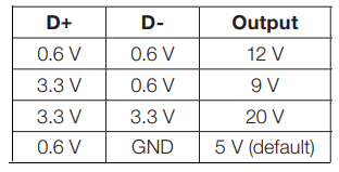
With the above table, I only needed 0.6 and 3.3 volts for D+, and GND and 0.6 volts for D-, which made it pretty easy because I could just use a couple signal relays to switch between the voltages. I also used a dual anode to common cathode diode to be able to control the D- relay regardless if I needed 9 or 12 volts since 0.6 was on the normally open leg of the relay. I also used a USB B connector because I wanted something robust. I put some ESD diodes in as well to try to dissipate esd from the mounting screws (and maybe remove any charge from the ABS plastic), but well, I didn't fully understand it and I learned fairly recently that I used them wrong. I wanted to via stitch the unused space for maximum heat dissipation, but I didn't to put all the vias in myself. Rather, I think I started to, but I looked for some other way instead, which was

I was forced to use an SPDT switch for power, since the SPST switch I wanted wasn't normally stocked. I can't remember if the SPDT or SP3T switch has a threaded bushing, but it was what I could get, even if the smooth bushing was what I wanted both to be. I used polyimide tape (aka Kapton tape) to insulate some of the vias or to insulate the parts from the vias just to be safe. Because the fan I was using had only 2 wires (and a two-position connector), I used a two-position header. I think it was after the boards came when I realised that the fan I had to cool the voltage regulator was 45mm and not 40mm, and I bought Noctua's 40×10mm fan as the fix.

I also found an interesting pattern on the bottom of the relay (I'm used to relay pottings not showing any sort of pattern).

It was a couple days later where I had it assembled.


I forgot which of Arctic's fans I used, but it eventually was replaced with the 80mm be quiet! fans that were in Pod's old case. Not too much to talk about with the work done on the ABS sheets, I used calipers to mark the locations of the screwholes and did my best to drill everything on location and as straight as possible.
It was after some usage that the fans just randomly shut off, and I don't think I thought anything of it until it did it again while giving off a smell similar to tooth dust. What had happened was that the tantalum cap went out, and that I had put it backwards because I thought the banded side of the cap was negative. I dunno where the standard for banding the positive side of tantalum caps came from, but I thought it was similar to SMT electrolytic caps and diodes. Anyway, I had spares, so I just plopped a new one on in the correct orientation and I was on my way. A weird thing about this board is that to be able to get to to 9 volts or 12 volts (I leave it at 5 volts by default), I have to switch it to 12 volts for a few seconds before I can either switch to 9 volts for 9 volts or switch to 5 volts and then back to 12 for 12 volts. There's actually a specific thing that I'm actually suppposed to do for proper initialisation (preferrably with an MCU) that Dangerous Prototypes found, but I was only concerned with the D+ and D- voltages back then.
Oh right, I did do a test where I pulled 9 and 12 volts for a bit with the 40mm fan disconnected, and the regulator did get warm/hot as expected, but with the 40mm fan on at 9 and 12 volts, the regulator and board stay cool. I thought I overengineered the board, but it seems like I actually did it just right. The 40mm fan kinda tries to spin at 5 volts, but it's not enough voltage in the pulse for the fan to turn. I think Noctua says the startup voltage is about 6 volts? Anyway, if I give a little nudge when the pulse happens (might just before, I don't remember), the fan will start moving (the fan runs at 5 volts, but won't start at 5 volts). I can also just give the fan 9 or 12 volts to get it spinning and then switch it to 5 volts, but there's no reason for the fan to spin at 5 volts.
I kinda had a thought to redo this board with an MCU because it would get rid of the relays and make the board a little more compact in z-height (especially if I move everything to the side with the USB B connector), but this board works just fine and I'm not sure I want to spend the time on the redesign. If I did redesign the board, I would likely tent the vias and then have certain vias exposed for heat dissipation.

DAP screen-down under a 120mm fan while charging.
I decided to build my own charging station since all the ones on the market had too many slots, were much larger than I needed, and didn't have a fan. I decided on some ABS plastic from TAP Plastics since I could have them cut into the sizes I need, and I was thinking 0.25 inch thickness would be fine, but I decided on 0.375 inch thickness just to be safe. The fans I decided on was two 80mm fans since that was the best size to keep the plastic sheets all the same size.
I also had a charger with QC (I don't remember which QC version), and decided to use that so I could manage the speed of the fans. I looked around on how the QC thing worked, and found a post where someone used an MCU to be able to get the other voltages. I only needed the voltages that D+ and D- would need to be at for the voltages I wanted (9 and 12), so the rest was brushed off because I was going to do it with discrete parts. Because I knew that stepping 12 (or even 9) volts down to 3.3 volts would heat up the voltage regulator, I was going to need a fan on it and I had a small fan for doing so. With the voltage regulator, I also went with a DPak package because I wanted it simple and beefy (even if the output is 500mA).
Voltages D+ and D- need to be at for a specific voltage.
With the above table, I only needed 0.6 and 3.3 volts for D+, and GND and 0.6 volts for D-, which made it pretty easy because I could just use a couple signal relays to switch between the voltages. I also used a dual anode to common cathode diode to be able to control the D- relay regardless if I needed 9 or 12 volts since 0.6 was on the normally open leg of the relay. I also used a USB B connector because I wanted something robust. I put some ESD diodes in as well to try to dissipate esd from the mounting screws (and maybe remove any charge from the ABS plastic), but well, I didn't fully understand it and I learned fairly recently that I used them wrong. I wanted to via stitch the unused space for maximum heat dissipation, but I didn't to put all the vias in myself. Rather, I think I started to, but I looked for some other way instead, which was
create_drill_line_array.ulp from Dangerous Prototypes. The script, rather user language program (ulp), worked well enough, but I found that there was certain things it didn't like, and also that it will stack vias on top of each other if you're not careful. Though I did the vias one line at a time, it was still faster than doing it one via at a time. I think it's time to show the board...
Vias, vias everwhere.
I was forced to use an SPDT switch for power, since the SPST switch I wanted wasn't normally stocked. I can't remember if the SPDT or SP3T switch has a threaded bushing, but it was what I could get, even if the smooth bushing was what I wanted both to be. I used polyimide tape (aka Kapton tape) to insulate some of the vias or to insulate the parts from the vias just to be safe. Because the fan I was using had only 2 wires (and a two-position connector), I used a two-position header. I think it was after the boards came when I realised that the fan I had to cool the voltage regulator was 45mm and not 40mm, and I bought Noctua's 40×10mm fan as the fix.

I also found an interesting pattern on the bottom of the relay (I'm used to relay pottings not showing any sort of pattern).

It was a couple days later where I had it assembled.


Mostly finished in its mockup location, bottom rear 3/4 view, bottom front 3/4 view with a leg removed.
I forgot which of Arctic's fans I used, but it eventually was replaced with the 80mm be quiet! fans that were in Pod's old case. Not too much to talk about with the work done on the ABS sheets, I used calipers to mark the locations of the screwholes and did my best to drill everything on location and as straight as possible.
It was after some usage that the fans just randomly shut off, and I don't think I thought anything of it until it did it again while giving off a smell similar to tooth dust. What had happened was that the tantalum cap went out, and that I had put it backwards because I thought the banded side of the cap was negative. I dunno where the standard for banding the positive side of tantalum caps came from, but I thought it was similar to SMT electrolytic caps and diodes. Anyway, I had spares, so I just plopped a new one on in the correct orientation and I was on my way. A weird thing about this board is that to be able to get to to 9 volts or 12 volts (I leave it at 5 volts by default), I have to switch it to 12 volts for a few seconds before I can either switch to 9 volts for 9 volts or switch to 5 volts and then back to 12 for 12 volts. There's actually a specific thing that I'm actually suppposed to do for proper initialisation (preferrably with an MCU) that Dangerous Prototypes found, but I was only concerned with the D+ and D- voltages back then.
Oh right, I did do a test where I pulled 9 and 12 volts for a bit with the 40mm fan disconnected, and the regulator did get warm/hot as expected, but with the 40mm fan on at 9 and 12 volts, the regulator and board stay cool. I thought I overengineered the board, but it seems like I actually did it just right. The 40mm fan kinda tries to spin at 5 volts, but it's not enough voltage in the pulse for the fan to turn. I think Noctua says the startup voltage is about 6 volts? Anyway, if I give a little nudge when the pulse happens (might just before, I don't remember), the fan will start moving (the fan runs at 5 volts, but won't start at 5 volts). I can also just give the fan 9 or 12 volts to get it spinning and then switch it to 5 volts, but there's no reason for the fan to spin at 5 volts.
I kinda had a thought to redo this board with an MCU because it would get rid of the relays and make the board a little more compact in z-height (especially if I move everything to the side with the USB B connector), but this board works just fine and I'm not sure I want to spend the time on the redesign. If I did redesign the board, I would likely tent the vias and then have certain vias exposed for heat dissipation.
Subscribe to:
Comments (Atom)