
DAP screen-down under a 120mm fan while charging.
I decided to build my own charging station since all the ones on the market had too many slots, were much larger than I needed, and didn't have a fan. I decided on some ABS plastic from TAP Plastics since I could have them cut into the sizes I need, and I was thinking 0.25 inch thickness would be fine, but I decided on 0.375 inch thickness just to be safe. The fans I decided on was two 80mm fans since that was the best size to keep the plastic sheets all the same size.
I also had a charger with QC (I don't remember which QC version), and decided to use that so I could manage the speed of the fans. I looked around on how the QC thing worked, and found a post where someone used an MCU to be able to get the other voltages. I only needed the voltages that D+ and D- would need to be at for the voltages I wanted (9 and 12), so the rest was brushed off because I was going to do it with discrete parts. Because I knew that stepping 12 (or even 9) volts down to 3.3 volts would heat up the voltage regulator, I was going to need a fan on it and I had a small fan for doing so. With the voltage regulator, I also went with a DPak package because I wanted it simple and beefy (even if the output is 500mA).
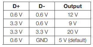
Voltages D+ and D- need to be at for a specific voltage.
With the above table, I only needed 0.6 and 3.3 volts for D+, and GND and 0.6 volts for D-, which made it pretty easy because I could just use a couple signal relays to switch between the voltages. I also used a dual anode to common cathode diode to be able to control the D- relay regardless if I needed 9 or 12 volts since 0.6 was on the normally open leg of the relay. I also used a USB B connector because I wanted something robust. I put some ESD diodes in as well to try to dissipate esd from the mounting screws (and maybe remove any charge from the ABS plastic), but well, I didn't fully understand it and I learned fairly recently that I used them wrong. I wanted to via stitch the unused space for maximum heat dissipation, but I didn't to put all the vias in myself. Rather, I think I started to, but I looked for some other way instead, which was
create_drill_line_array.ulp from Dangerous Prototypes. The script, rather user language program (ulp), worked well enough, but I found that there was certain things it didn't like, and also that it will stack vias on top of each other if you're not careful. Though I did the vias one line at a time, it was still faster than doing it one via at a time. I think it's time to show the board...
Vias, vias everwhere.
I was forced to use an SPDT switch for power, since the SPST switch I wanted wasn't normally stocked. I can't remember if the SPDT or SP3T switch has a threaded bushing, but it was what I could get, even if the smooth bushing was what I wanted both to be. I used polyimide tape (aka Kapton tape) to insulate some of the vias or to insulate the parts from the vias just to be safe. Because the fan I was using had only 2 wires (and a two-position connector), I used a two-position header. I think it was after the boards came when I realised that the fan I had to cool the voltage regulator was 45mm and not 40mm, and I bought Noctua's 40×10mm fan as the fix.

I also found an interesting pattern on the bottom of the relay (I'm used to relay pottings not showing any sort of pattern).

It was a couple days later where I had it assembled.


Mostly finished in its mockup location, bottom rear 3/4 view, bottom front 3/4 view with a leg removed.
I forgot which of Arctic's fans I used, but it eventually was replaced with the 80mm be quiet! fans that were in Pod's old case. Not too much to talk about with the work done on the ABS sheets, I used calipers to mark the locations of the screwholes and did my best to drill everything on location and as straight as possible.
It was after some usage that the fans just randomly shut off, and I don't think I thought anything of it until it did it again while giving off a smell similar to tooth dust. What had happened was that the tantalum cap went out, and that I had put it backwards because I thought the banded side of the cap was negative. I dunno where the standard for banding the positive side of tantalum caps came from, but I thought it was similar to SMT electrolytic caps and diodes. Anyway, I had spares, so I just plopped a new one on in the correct orientation and I was on my way. A weird thing about this board is that to be able to get to to 9 volts or 12 volts (I leave it at 5 volts by default), I have to switch it to 12 volts for a few seconds before I can either switch to 9 volts for 9 volts or switch to 5 volts and then back to 12 for 12 volts. There's actually a specific thing that I'm actually suppposed to do for proper initialisation (preferrably with an MCU) that Dangerous Prototypes found, but I was only concerned with the D+ and D- voltages back then.
Oh right, I did do a test where I pulled 9 and 12 volts for a bit with the 40mm fan disconnected, and the regulator did get warm/hot as expected, but with the 40mm fan on at 9 and 12 volts, the regulator and board stay cool. I thought I overengineered the board, but it seems like I actually did it just right. The 40mm fan kinda tries to spin at 5 volts, but it's not enough voltage in the pulse for the fan to turn. I think Noctua says the startup voltage is about 6 volts? Anyway, if I give a little nudge when the pulse happens (might just before, I don't remember), the fan will start moving (the fan runs at 5 volts, but won't start at 5 volts). I can also just give the fan 9 or 12 volts to get it spinning and then switch it to 5 volts, but there's no reason for the fan to spin at 5 volts.
I kinda had a thought to redo this board with an MCU because it would get rid of the relays and make the board a little more compact in z-height (especially if I move everything to the side with the USB B connector), but this board works just fine and I'm not sure I want to spend the time on the redesign. If I did redesign the board, I would likely tent the vias and then have certain vias exposed for heat dissipation.
No comments:
Post a Comment