24 March 2016

2(DrivePi)

With how long it's been with these projects and everything happening else between then and now, it's really difficult to remember all the details - please bear with me. (A quick notation to those that haven't noticed by now.)

Early February of last year, I wrote a couple posts that I was considering a Raspberry Pi 2, and the fact that it was six times faster than the B+ made it more appealing.

At some point I ended up finding a dual-core ARM board that was released as competition to the Raspberry Pi called the Banana Pi, which has gigabit ethernet and a SATA port. I was quite interested in it for using it for my bittorrent server, considering I can properly hook up a hard drive and be able to pull files off of said hard drive over the LAN much quicker.

I believe it was around early May that I began thinking of how to mount everything - the Raspberry Pi 2, the Banana Pi and the 2.5" hard drive. I drew quite a few designs and my friend at work gave me the suggestion for a 3D-printed case, which I didn't feel was going to be worth it. I originally wanted the case to have separate layers for each item and have the airflow in a certain way where it would effectively cool each item (there would be a fan that pushes the air out). I eventually realised that it would be space efficient to have a case that mounts to the back of a monitor, so it takes up less table space, and I took quite a bit of time to pick out a good box before drawing up anything else.

I then spent quite a bit of time figuring out how I wanted to arrange the parts inside the box, since I wanted to try to have a good airflow so the parts stay relatively cool. I think I went through a few ideas with the fan on the side wall (in relation to the box itself) before realising the fan hole would be fairly difficult to cut.

Eventually I found a couple of unused blower fans back from when I was trying to keep Ziggy cool, one of which didn't have wires because they broke off. I soldered a pair of wires to it and tested it, finding that it worked just fine, so I decided to use that instead of the regular case fan.

Since I was going to have another hard drive to keep my music files local for the Raspberry Pi 2, I had to keep the arrangement simple enough, and using an adaptor for mounting two 2.5" hard drives in a 3.5" bay was the way to go. I eventually decided to have the hard drive stack sit in the middle of the box, toward the side (again, in reference to the box), have one of the single-board computers (SBC) to one side of the stack, and the other to the other side (upside-down), with both SBC toward the opposite side (in sort of parabolic curve); the fan would be attached to the lid and blow out of the side.

Luckily, I waited long enough and a new version of the Banana Pi came out which had a bit of improvements, and so I bought it along with most of what I needed. I carefully drilled the hole patterns for the hard drive, the Raspberry Pi 2, the Banana pi, and VESA mounting before doing a bit of prototyping with the boards and box.

I used some of the stand-offs that I bought to mount that PCI-E adaptor thingy that I put in Melty to stand off the SBCs, and eventually found that I was going to need more than just one to properly run all the cables. I ended up using four for the Raspberry Pi 2 and six for the Banana Pi. Since using a bunch of the stand-offs wasn't exactly straight, I decided to look for something similar in height for both. For the Raspberry Pi 2, I used a 30mm stand-off (which accepts screws on both sides, lowering the height from the prototyped 32mm), and 50mm for the Banana Pi (accepts a screw on one side, raising the height from the prototyped 48mm). Luckily, the two millimetre difference of both stand-offs were really negligible when I prototyped it again.

When prototyping the first time, I realised that the adaptor brackets blocked the lower holes for the VESA mount, so I originally came up with that I would mount the lower hard drive to the box, mount the box to the monitor, then mount the bracket-attached upper hard drive to the lower one in a really awkward way. Eventually I had a "kickself" moment and grabbed some scrap aluminium sheets from work and made my own mounting plates, so that the lower screws wouldn't be blocked off (and also saves the adaptor bracket for its intended use).

With that, I carefully drilled the intake hole horizontally centre between the holes to the hard drive mounting a bit toward the bottom of the box (in relation to it's mounted configuration), cut the hole for the blower fan, and drilled the holes for mounting the blower fan. I think I also cut the holes for the cables at this time as well. The holes that I cut were awkward to do, since I was using a jeweller's saw, and if I had the right bits for the high-speed drill, I probably would have used it.

Inside, backside, and inside bottom of the box.

Since the only button-head screws I had were metric (there's a very small selection of small button-head screws at work), they ended up being much longer than I needed, and I prototyped a bit to figure out how much I'd have to cut off, which definitely easier said than done. I used button-heads because of the low profile, and I wanted to keep air resistance to a minimum since the heads were to reside inside the fan.

I made the mistake that I wouldn't be able to tighten the nylon locknuts or properly assemble the fan while doing this, and so I had to drill a couple more holes in the fan's case, so that I could access the screws. I obviously covered the holes with electrical tape and cut off the angled part of the metal bracket (which can partially be seen in the top view picture).

Inside, outside, and top of lid with fan attached.

Though it wasn't really needed, I kept the silicone seal piece in the lid (I had to actually remove it to cut the hole because it was annoying). I then cut a square of the mesh stuff that I bought as a filter for the side panel for Mei-chan and taped it on the outside of the box over the hole. I tried not to cover the holes, but I found I hadn't much choice and cleaned the holes with an X-acto knife.

Inside and outside of the box with the mesh (I propped the box up for the inside view because the mesh blended into the carpet).

With the mounting plates, I taped the two pieces together, so that I could drill two holes at once, and it was somewhat awkward to mark the holes from the adaptor bracket, but the holes came out just fine. It was a bit tough to position the holes right, because I wanted to where it directed the airflow some, keep the drives apart enough, so that it wouldn't interfere too much with each other (because I had it planned where the tops of the hard drives would face each other), and not have the holes too close to the edge of the metal.
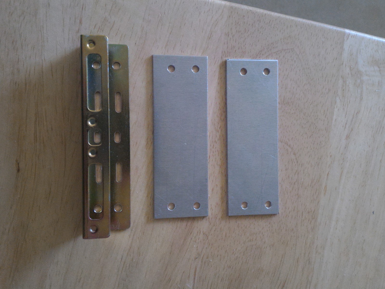
Adaptation bracket, and the two mounting plates.

Sometime during testing, the Raspberry Pi 2 wasn't able to power the hard drive I wanted to use, so I was forced to buy an SSD for it (the Raspberry Pi 2 literally puts out no more than 500mA, and the hard drive I was trying to use needed another 50mA :T).

I just remembered that I wanted to space the hard drive apart from the SSD so that the SSD has a less likely chance to absorb heat from the hard drive (in retrospect, just something that really wouldn't matter). Anyway, after assembling the hard drive unit together, I realised that I could've lowered the mounting plates a bit more to really direct the airflow. Que sera sera.

Top 3/4 view and "bottom" view of the unit.

Since the stand-offs are screwed into the bottom mounting holes of the hard drive, I had to use some washers to reduce the length of the screws to the mounting plate. The threaded portion of the stand-offs were too long for the bottom mounting holes of the hard drive, so I used the included nut to reduce the length. I believe I used thread-locking compound for (at least) the bottom mounting screws to the mounting plates, so that the vibration doesn't loosen the screws.

3/4 view of the washers, and bottom view of the unit.

After assembling the hard drive unit, I mounted it into the box.

Inside and outside with the hard drive unit mounted.

Then I mounted the SBCs (after plugging the fan into the Banana Pi, since it's "upside-down") and mounted it to the monitor. I used a washer between the screw-head and the box since the plastic was a bit soft (I don't remember if it's ABS, poly-carbonite, or a mixture of both). I used a spacer between the box and the monitor, so the intake wasn't clogged, along with keeping the screws and nuts from pressing into the monitor (or worse, warping that side of the box). As I positioned the lid, I routed the cable to the fan, so that it wouldn't get sandwiched on any of the seams. It turned out quite well, minus the hand-cut screws protruding from the nylon locknuts.

Finished inside, outside, and top.

I had the Raspberry Pi 2 hooked up to the DVI port and the Banana Pi to the VGA port, and use the monitor's menu to switch between them (when needed).


Later, I got the button-head screws in the right length, so that it would be flush with the "top" of the nylon locknut to look nicer.

Colour is slightly off because of the flash.

Later I did some experimentation with the command-line interface of transmission and found it wasn't all that bad, so I decided to redo the Banana Pi a bit, so that I wouldn't need the monitor (or Bluetooth adapter). While I thought it'd be simple, it was a bit different than I was expecting (the folder was a bit different because the folder the CLI uses is transmission-daemon and not transmission. Once that was figured out, it was up and running in openSUSE Tumbleweed instead of the Banana Pi openSUSE image.

The Raspberry Pi 2 is better than the original Raspberry Pi (generation one), but still don't see the 1080p playback (again, with XFCE and VLC)... Whatever.

With the announcement/release (I don't remember off the top of my head at the moment) of the Raspberry Pi 3, it will be replacing the Raspberry Pi 2 after some testing. I might run Debian testing on the Raspberry Pi 3, but we'll have to see. The reason why I want to do this is because the Raspberry Pi 3 has built in Bluetooth (and also WiFi, which will be turned off), which saves me a USB port. It also has a bit of a performance increase, but I'm not expecting much. There's also the ARM64 architecture, but I'm doubting it'll have any visible impact either.

As far as the name goes, I took a few days to think about it, eventually turning "double drive-by" to "double drive-pi" because there was two "pi's" and two hard drives. I quickly put the "official" name in mathematical notation - 2(DrivePi) - where "DrivePi" is each Pi and hard drive combination, and the 2 in front of the parenthesis multiples the parenthesis' contents by two (in other words, doubling). I kinda want to have it on the lid, and use the screw/nylon locknut protrusion for the dots of each "i", but it wasn't going to be doable. Well, I had thought about it again, and I could very well put the two at the end, though it technically would be read "drive-pi doubled" instead. I'll worry about it when I actually care.

That's all on the 2(DrivePi) for now. It's not 100% complete, but at least it's well over 90%.

Ikea Lamp Modification

I bought a couple LED lamps from Ikea a few years ago, one of which I used for my makeshift soldering station. I had used double-sided adhesive foam to attach the switch to the base to make it more accessible, and every so often the light would go out, which was usually fixed with putting pressure on the switch.

I lived with it until late 2014, when I took the switch apart to find nothing wrong with it. Since I was going to incorporate the light into the switch for my soldering station, I hooked it up to the switch it was going to be connected to and used that, until I couldn't hack the light back on after it turned off.

 The next day I removed the wires from the switch and soldered them together, which eventually yielded the same result of the lamp turning itself off. I think I measured the voltage from the adapter and found that it was working fine before directing my attention to the head of the lamp. I think I found the head hot to touch, so I knew something was definitely wrong.

At some point I opened up the head and found a PCB with three things on it: an LED and two SMD parts (SOT-223 case) - I wasn't sure what to make of it as searching the numbers on the part yielded nothing. As I look back now (now that I've learned quite a bit), they more than likely are voltage regulators connected to regulate the current to the LED, and it's more than likely that one of the regulators became bad or was bad to begin with.

Back then though, I figured the LED was being over-volted (where 4 volts was too much), and played with it with my bench-top power supply to find that I could definitely power it with less voltage. I set it aside because I didn't want to spend any more time with it, and it sat for a few months before I decided to do something about it.

About the middle of last year, I decided to look at it again, and I had forgot what voltage output of the original adapter and started at 9 volts, which blew one of the regulators. I think I grabbed the adapter and looked at the voltage and decided to find a good voltage under 4 volts. Anyway, I found that 3.3 volts would definitely be doable, and then looked for a 3.3 voltage regulator.

Then came the next problem, I would need to find an adapter that met the minimum input voltage (and amperage) for the voltage regulator, but luckily I had one that was more than plenty. I could have used an LM317T voltage regulator, but I wanted the modification to take up as little space as possible (not to mention that I'd need an input of at least 1.5 amperes.

I drilled three holes into a small potting box that I found at work (I'm not sure if the potting boxes were used for something or not at one point) before stuffing the wires through and soldering the wires and regulator legs appropriately. I attached the regulator to the top-inside with an insulating shoulder washer and a 4-40 x 1/4" screw and a nut. Luckily I had also found a bottom for the box, which I had fastened to the base of the lamp with double-sided adhesive foam.

The regulator attached to the top-inside of the potting box, better picture with flash, the bottom "lid" affixed to the base, and the box "secured" to the base.

At some point before this, I had grabbed the other lamp as sort of a cross-reference and while it did get warm, it wasn't scalding like this one was. Anyway, because of the adapter that I used to power the regulator and the lamp, I decided to use this for the dim light for my bedroom (usually used before I go to bed). It worked just fine, though it was a bit dimmer than I expected, until I left it on for a while, to which it turned off again.

Needless to say I was confused again, and I looked at the lamp with the regular light on. I found that the regulator was putting out a lot more heat than I had expected and it melted the plastic some. Since I immediately investigated, the plastic and screw were still hot.

The outside and inside of the potting box where the regulator was. (Picture was taken after the new case was completed.)

Luckily I found some scrap aluminium alloy blocks and an unused aluminium case as well, both of which I took to use to remedy the solution (along with some electrically-insulating thermal pad scraps and some 4-40 taps). The aluminium alloy was a pain in the arse to drill through, even with a good cordless drill, but I had gotten the hole I needed.

At least I thought I had. The hole I drilled was too large, so the tap wasn't able to do anything. I drilled a smaller hole, which I thought worked, until I broke the tap... Oops. I then looked up the correct drill size and found the closest that I had, which was bigger than the #43 that I needed, but worked just fine.

With the "correct" drill size, I then positioned the block to where I'd like it to sit in the case and drilled a hole through the case and into the block, following up with a slightly larger drill bit through the case itself to allow the screw to pass through.

I drilled a few more holes in the case for the wires and for some slight airflow. The top and bottom are aluminium sheets, since the original top and bottoms were nowhere to be found and I didn't want to spend any more than I already had to buy the proper lids. The top lid received extra holes for slight airflow, while the bottom screw holes were countersunk for use with flat-head screws for easier mounting.

Since I had to remove the regulator from the potting box, I had to redo the soldering a bit, and made it a bit neater when I soldered it back together - soldering both ground wires to one wire to the ground leg (centre leg) of the regulator instead of both ground wires like I had done before.

I mounted the regulator to the block (with the thermal pad between them and using the insulating shoulder washer) then slid the block into the case before securing the block to the case.

The regulator attached to the block, different angle, block secured to the case, extra space inside the case, block spacing from the bottom of the case, the screw securing the block to the case (as well as the output cable), and the air holes on both sides of the case,

I then did a bit of cable management at the top before leaving the rest for the next day.


The next day, I soaked what I couldn't scrape off of the double-sided adhesive foam with Goo Gone while I attached the top and bottom pieces to the case.

Finished top and bottom.

Once the base was clean and dry, I adhered the case to the base and returned it to its spot in my bedroom.

"Near" and "far" sides.

The block and the case definitely dissipates the heat from the regulator without any problems at all - I probably didn't even need the air holes. I did a test where I left it on for several hours and the case wasn't even warm, so it was good to know that I shoddily engineered something that excessively exceeds its purpose.

I think after the metal casing the light is dimmer and maybe brightens over time, but it works out just fine for what I use it for. Maybe I'll properly fix it at some point, or maybe just buy a new lamp (it's about 10 USD each if the prices haven't changed)... Or maybe just leave it be.

Solder Fume Fan 2

Last night as I was in bed, I realised I forgot a couple things.

I originally mounted the solder reel on the "upper" part of the leg, but it was just as troublesome compared with where the reel originally was.

With the screws to mount the LED array, I switched the half-inch long 4-40s for 3/8 inch instead when I found them in a massive bag of screws that was in my area.

And there are two screws that attaches the brass ball holder to the L-bracket to prevent rotation.

23 March 2016

Solder Fume Fan

At work, there was a couple benchtop solder fume extractors, one that I used and another that sat off to the side. I kinda was a bit annoyed that it used an AC fan which was loud and didn't seem to move much air (even without the filter), so I decided to make it more efficient with a DC fan and add in a light while I was at it.

I grabbed a 120mm case fan with the highest CFM that I could find from the local computer store, since I didn't want to wait for a package in the mail. If I remember correctly, I already had the LED light array on hand, so I didn't have to wait on that at all. I decided to use the extractor that wasn't being used, so I didn't have to deal with the hassle of not having something readily usable if I didn't get all of it done during lunch.

Mounting the fan was a bit weird, since I had to use two of the screws packaged with the fan to mount it to the front grill of the housing and use two of the original screws to mount the front grill to the rear housing. Luckily with the fan I chose, I was able to remove the unneeded corners, even though the original screws fit through the holes just fine (I think?).

The fan screw attaching the fan to the front grill, and the extractor screw holding the grill to the housing.


Mounting the LED array was slightly trickier because of the curved surface, but I found some #4 spacers that were a good length and used that in combination with 4-40 x 1/2" screws and nylon locknuts. I tied the wires to the LED array with the fan at the switch, so when the switch is in the on position, both the fan and the light come on. I was also fortunate enough that the 22 AWG wire that I used for the light fit through nicely between the top of the grill and the housing.


Close-up of the light mounting, the mounting at the top of the fan, unit off, and unit on.

It's hard to describe how bright the LED array is, but it's something you really don't want to look into too often or for too long. It does get warm, but isn't really a concern (or at least I'm hoping not). Anyway, there were some unused 12-volt power supplies at work, and I used one of them for the project, feeding the cord into the housing with a strain relief that we also to happen have.


I don't use the filter, since I don't mind the smell of flux - it's just to pull it away from my face. I stuck with it for a while, but then decided to upgrade it a bit since it wasn't really usable with a vise that I use to hold parts to solder. I eventually found some parts that I was able to use to build new legs to enable it to stand taller so that I could use the vise and the fan. I didn't get a chance to take any pictures before I modified it again.

I then found some other parts that I used to move the solder reel closer so I didn't have to reach across the desk (and have an excess length of solder). I also attached a screw to the lower part of the right leg to kinda trap the brass ball holder so it wouldn't run away from me while I'm stabbing it. Eventually I got some SPST on-off switches, and also added it to it, so that I could turn the light and fan on independently of each other.

Close-up of the added SPST toggle switch, overview of "version 3", close-up of the solder reel mounting, close-up of the brass ball stopper screw, and a close-up with the brass ball holder in place.


I was a bit slow to take pictures because I didn't get a good chance to properly test it (i.e. use it for extended periods) and I was unsure if it was going to stay that way. The other reason for the delay was because of the company move, and so it resided in a box partially disassembled (just enough so that the pieces lay flat.

Eventually I didn't really like the solder reel being on the inside, and so I moved it outside, but then the spool itself became another problem - making it hard to draw solder when necessary (mainly at the seam of the spool). I really liked the openness that I created because I was able to fit the vise however I needed, but didn't want to deal with the awkward draw when I hit that seam. The other thing that got annoying is that the ball holder kept rotating, which eventually made it difficult to stab properly.

I mounted the brass ball holder to an L-bracket and mounted it to the leg, which raises the leg a bit, but there wasn't much of an option otherwise. With the solder reel, I fashioned a couple brackets to hold a shoulder bolt, but found it would be easier to draw the solder if the radius of the bolt was larger. At first, I used a couple plastic spacers which I thought would be fine, but the solder would either work its way between the spacers or between the spacer and the bracket, so I had to look for something taller. I think I also had a problem where the bolt wasn't tall enough as well.

Anyway, after getting a taller shoulder bolt and finding a couple metal spacers, it worked well, but I was then presented with yet another problem When I pull too much solder and push it away from the workspace, it'd fall of the side of the bracket and get caught on the bracket edges. I grabbed a smaller shoulder bolt to remedy this, but had to disassemble the brackets a bit to grind enough of one of the brackets away to allow for the nylon locknut to sit flat against the other bracket. I found it worked decently to keep the solder from going over the edge, and went with it.

Close-up of the brass ball holder and bracket, close-up of the solder reel section, right side of the solder reel section, and the overview of it all.

While using it recently with the vise, I found that the solder went over the short shoulder bolt on a few occasions. I first went for the same shoulder bolt that I used, but then realised that I probably wouldn't have space for the nylon locknut because of the screw and nylon locknut that holds the two brackets together. I found a screw that was definitely long enough, but was kinda weary with the threads.

I took the screw back with me and found that if I added a jam nut, it might give me the space I need to raise it to the same height as the shoulder bolt. It didn't, so I went back for another jam nut and found it was just slightly taller, which I was fine with, until I realized at the fastener cubby that I could just use one nylon locknut instead. The next problem was the remainder of the bracket that was ground down some. The nylon locknut would might have barely fit, but I didn't want to take it all apart and try to carefully grind it down to the bare minimum, so I opted for a spacer instead.

It took a few minutes, but I found one that was perfect (albeit taller than necessary, but it didn't matter), so I removed the leg and the solder reel and went to bore out the hole to fit the screw that I found. I ran into another problem, but it was from partially rushing to finish the modification quickly. The drill I used is the exact same size as the screw I had, which means the screw very tightly fit inside the bored hole. At first I thought that the drill was the wrong size, but then realised I'm supposed to use a slightly larger drill bit. I walked across the "warehouse" to grab a very slightly larger drill bit, which fixed the problem within seconds.

The new "blocking pin", and the close-up of below the brackets.

Unfortunately I haven't been able to fully test this, as I had just took the above two pictures just a couple days ago, but in theory, it should be just fine. The bottom part of the legs was made from one piece, which was cut into two (with one being slightly longer than the other because I didn't take enough time to measure it). The "top" part of the legs is made with a bracket that is used to hold a switch box at the end of an armrest. The adjustable part of the legs is made from two matching pieces, and is tightened appropriately, so that there is adjustment in two out of three joints.


The knob for the housing is the original part, since it's either a metric or odd-ball screw/nut combo, but luckily, the piece isn't too thick to render it useless.

I also had made a thing that I used to rest the solder on, so it would be easier to pick up, which I originally had to modify because of the reflection of the lighting array, but I no longer needed it after relocating the solder reel. While I used to use the light occasionally at the old location, I now use it a bit more frequently because of how dark the deeper half of my room is (the lighting fixture needs a new ballast).

Anyway, I think that's about all that I'll be doing to it... Unless I actually design, draw, and have parts made for a cleaner version (highly doubtful on the latter).