For being able to test the custom controller without having to spend money on the board (especially when I wasn't sure if I'd be buying the board without the joysticks or buying the one with joysticks that hadn't been designed yet), I needed at least a development board with the same MCU that the controller would use (ATSAMD21G18A-A). Between Adafruit and SparkFun, I couldn't seem to find a board that gave me access to all of the pins, since Adafruit's usually has a NeoPixel or DotStar along with a discrete LED taking up pins, and I don't remember what SparkFun's was like besides being much larger and pricier than I wanted. The solution was to make my own that has all the pins broken out, is as compact as I can get it while keeping compatibility with 2.54mm pitch headers, and has no extra frills (SparkFun's has one or two extra power inputs).
First thing I had to figure out was what size headers I needed and how to arrange them to keep it as compact as possible without having multiple rows of pins so that it's easy to label. I tried a few sizes and plugged them into my EAGLE helper programme to estimate the cost and took the best one, which was 16 pins by 9 pins for the 21G. By this time I had a standard of keeping the MCU on the same side of the board as the USB mini-B jack so that the D+ and D- lines are easy to connect, which I continued to follow as I placed the jack on the left of the board and placed the MCU roughly in the middle (probably towards the right more). Airwiring the pins to the vias for the headers ended up pretty easy, as the left bottom vias connected to the pins next to the USB pins and I worked my way anticlockwise with both the pins and the vias. For the traces, I started with the bottom pins/vias because it was hard to tell if there was enough space to fit all the traces there, and there was enough space for all of them with the MCU centred vertically. I had to shift the MCU leftward to tighten some of the traces up more, so I kinda had to redo those bottom traces, but I think it ended up looking nicer. The reset button was pretty easy to place with plenty of space on the bottom, as well as the components on top, but the capacitor for the MCU's core voltage (VDDCORE) gave me a bit of trouble for placement because I needed to avoid the silkscreen but keep it as close as possible. I feel like I might've redone part of the 3.3-volt rail to make it easier to place the VDDCORE capacitor? Anyway, I added an LED on the 3.3-volt rail to indicate if there is power or not (another one on the 5-volt rail from the USB would make it easier to diagnose if the voltage regular is working or not, but I didn't think of it then). Running SWCLK and SWDIO to the programming pads was somewhat tricky, and I had to use a slightly smaller trace size, but that's really all that was needed to make the traces as short as possible. Because of one of the vias possibly interfering with the silkscreen dot for MCU positioning, I had to place another one just in case (I think it kinda was okay?).
Very Teensy-looking.
The headers are split up as such because I was only going to buy a couple sizes and break them down accordingly to fit because the 16-position headers were either unavailable or non-stocked. Anyway, the board for the 51J didn't go nearly as easily because of the increase in amount of pins, and I spent quite a bit more time with different layouts compared to the 21G. I think the most ideal board size would leave 3 vias unplaced, and I was also considering having one via come in towards the centre on the bottom and top at the left side, but that would've still left one via still needing placement. I eventually went with a 13 by 12 layout because it was the best that I could do while keeping the board cost as low as possible. I went with the same idea of starting with the pins next to USB and working anticlockwise for doing the airwiring, and also started with the bottom traces first. Even though there were a couple more parts to this one, there was much more space for placement, though I think I redid a couple traces to make it easier to do the reset button. Since I was copying part of the schematic from Adafruit's boards, I only have one capacitor for 5 volts on this one instead of two. Really not a whole lot to say, since there's really not much different than the other one.
See? Not too much different.
The 21G dev board would cost me about 7.19 USD (per three), the 51J dev board would cost me about 12.60 USD (per three), and with both of them totalling 20.79 USD, it makes it cheaper than the 23.50 USD that the custom controller board would cost. Not only is there a savings of 2.71 USD, it saves me from having more boards in my "graveyard" of boards, since the dev boards are much more reusable.
The boards were ordered with a bunch of other boards and their parts were ordered with a bunch of parts for other boards (I feel like I've said this before...), and when going through the parts, I found that Mouser put the ATSAMD21G18A-A MCUs in a regular static dissipative bag instead of the moisture barrier variant, but the ATSAMD21E18A-A and the ATSAMD51J19A-A were packaged correctly (the MCUs have a moisture sensitivity of level 3, or 168 hours). I can't remember if I had the boards first or the parts first, but regardless, I soldered the 21G MCUs to the board as soon as I could, and I haven't seen any weirdness so far. "What's the big deal with MSL?" you might ask? Well, moisture isn't great for certain semiconductors (ICs or not), and for stuff like MCUs, it can make operation wonky. For example: at work, one of the MCUs I work with isn't being stored in accordance to MSL specifications, and when I recently used 14 of them, I had to replace 2 of them because they were the source of a secondary output signal not operating. So yes, the MCU ran the firmware fine, but moisture damaged the operation of a pin. Ideally, the MCU should've been baked in accordance to MSL specifications before use, but I don't have that sort of capability at work, and there's no guarantee that just putting it in the reflow oven for a reflow cycle will dry it out properly. Though I say this, LEDs can be moisture sensitive too (as I mentioned a bit here), but for basic LEDs, it's probably not nearly as important to follow, unless you want reliability across 100% of the LEDs being mounted.
Anyway... The plan I had was to only populate one of the three boards with headers because three of the same board is a lot and the testing for the custom controller required me to make a lot of ground connections, which would be easier to do with the board having vias and not headers. Also the power LED turned out a lot brighter than I thought it would be, but all I would have to do is change out the resistor for a higher value (whenever I do it). Both MCUs were easier to solder under magnification instead of by eye, but that's maybe obvious? It was sometime after this batch of boards that I learned how to tent vias, and I would've done so with these dev boards had I known. Que sera sera.
51J boards, use your imagination for the 21G boards.
I haven't used the dev boards nearly as much as the Trinket M0 or the ItsyBitsy M4 that I have (I purchased the ItsyBitsy M4 with the one shrouded header I needed so that shipping would be more reasonable... I wouldn't have it if I properly counted how many of those headers I needed before making the order), but they're there when I need them. I also made some adapter boards for the flash chip that would socket into the boards with headers to expand the flash space, but I haven't had the boards made because I haven't needed extra flash space. I'd also have to build CircuitPython with the flash chip included in the config, but that's pretty easy (I'd just have to remember to have the adapter board connected before changing variants). I did think of using either dev board to try 8-bit character LCD communication (since I'd have more than enough pins to be able to), but I probably would have to write my own library for that, since Adafruit's library is 4-bit only. Reasoning for trying it is because it should be twice as fast to update the LCD, so on a 20×4 LCD, it should post the entire screen "instantly" compared to 4-bit, which has a slight lag with the fourth line.
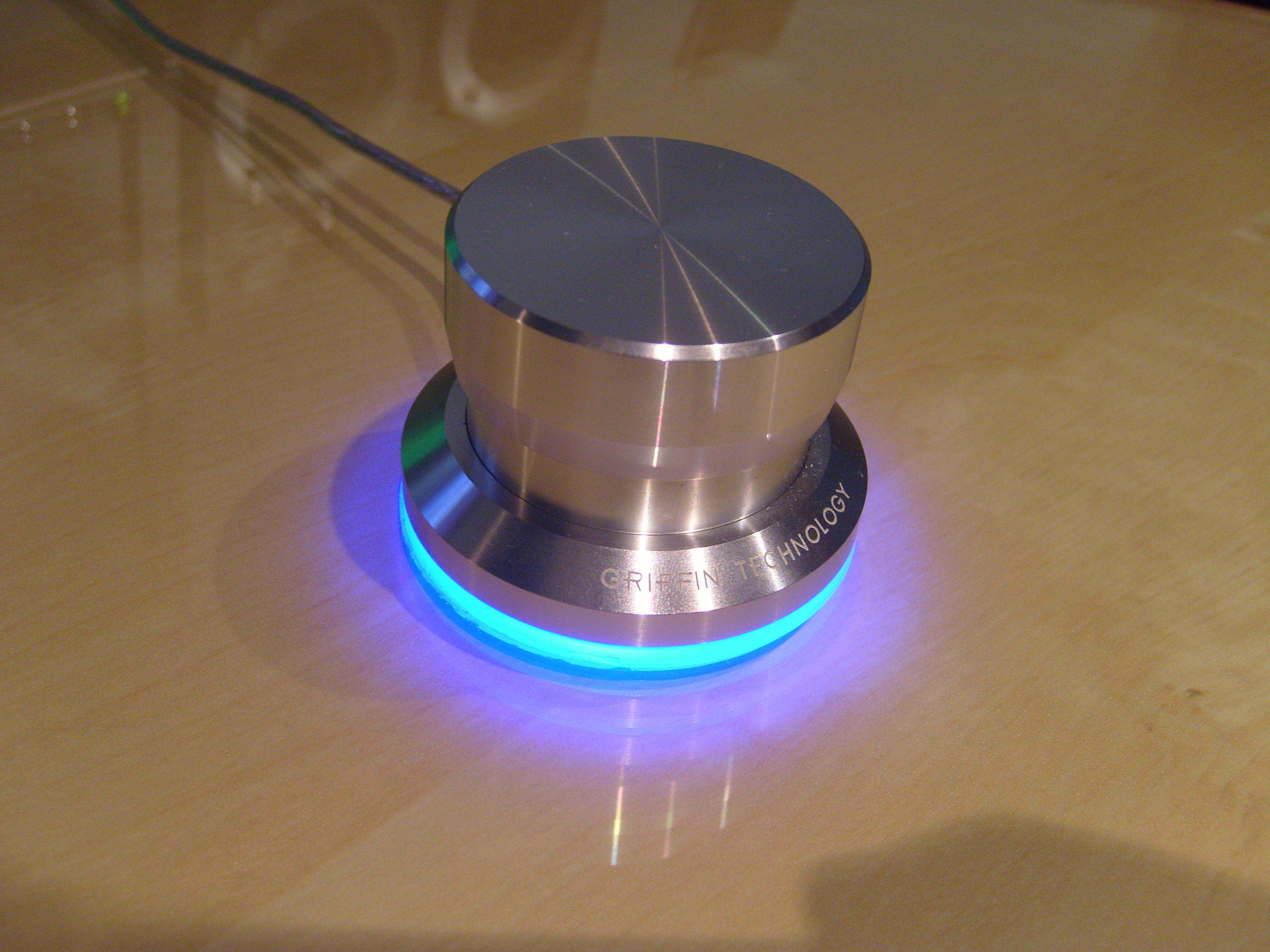
A friend and I both have a Griffin Powermate that we bought around 2008, which we used for various things, and while it was great in Windows XP, it was pretty much non-functional in Windows 7. There were forums and such saying to use the Vista drivers and running the software in compatibility mode, but neither my friend nor I could get it to reliably work, and so we both stowed it away (or at least my friend did).
I think it was while I was poking around Adafruit or something when I encountered the rotaryio library or the rotary encoder guide, but regardless, it got me thinking about the Powermate. It's a bit hard to remember this initial stuff, since I was also kinda deep diving with MCUs and CircuitPython, as well as working on the 3DS input redirect controller and some other MCU projects.
Anyway, the first thing was trying to figure out how to get the thing apart without doing too much damage or creating more work later, and I asked my friend if they still had theirs, to which they replied that they did. I wanted an extra as sort of a "sacrificial lamb" in case worst comes to worst, though I did also have a link saved to an ebay listing for buying one. One of the images on the ebay listing shows the top cap popped off, and when I was able to try it out on mine, I was stupified on how easy the cap was to take off, but to be fair, I never had a reason to pull the cap off or even try it (and neither did my friend). Below the cap on the main body is a little felt piece that I kinda ignored because I saw a nut that was holding the rotary encoder to the main body, but unfastening the nut didn't yield any meaningful results. Because there is a sort of gap between the bottom and top pieces (you can see this in the above image, especially at full-size), it was more likely that the body is made from two pieces of machined aluminium that were assembled in some way (either by press-fit or some sort of threading).
When I got my friend's Powermate, I first tried to twist the two parts apart, but I couldn't find channel-lock pliers that were large enough for the base (nor did I want to buy one large enough for doing so), and I wanted to avoid the pipe wrenches at work because of the lack of curve in their jaws. I also tried a trigger clamp, but it ended up slipping from the lack of surface area. Looking at the bottom at the glue that attaches the plastic to the metal, I found a somewhat large spot that the glue didn't spread to (the glue is white btw), so I decided to use the Jimmy pry tool (iFixit) to see if I could pop the bottom off, and well, it was quite easy. I unfastened the nut and went to to desolder the USB wires from the board, which gave me a better look inside, and I saw a more obvious seam between the parts on the inside. I think I tried the pointy side of the metal spudger (again, iFixit) between the moulded strain relief for the USB cable and the bottom part of the body, and it did slowly give, but because of the strain relief compressing, it made it tough to free the bottom piece. I think if I had two metal spudgers, it would make it easier to separate the parts, but I still got it apart with just one. I felt a little stupid for not trying that before popping the plastic piece off of the metal, but it wouldn't be too hard to glue it back on.
With the new separation strategy, I applied it on mine to be able to get the board from mine, and because I was already at the soldering station, I went and desoldered the rotary encoder from the board, which was easier said than done with a small cone tip (I should've used the larger cone tip for more thermal mass). With the board and rotary encoder, I went to pull measurements for the footprint I would need, and it was a little tough since I damaged some of the vias and ripped off one of the retention pads. Measuring the vias was a little tough, even with pin gauges, but I think I ended up with something that worked, and even getting the placement of the rotary encoder footprint position on the board was also a bit tough since the board has what someone calls "mouse bites" at the north, south, east, and west locations (which can be seen in the larger versions of the board images below).
Bottom of the board, top of the board, body bottom (with marring from the metal spudger).
The board was fairly easy to design, since I was using an ATSAMD21E18A-A, which fit in between the button and encoder legs of the rotary encoder, and I had to put a reminder in my notes that I would need special pads for connecting the programmer to the board and that I would need to figure something out for the reset button. For the lighting, I went with sixteen RGB LEDs (specifically, WS2812B-2020 aka NeoPixel Nano 2020 from Adafruit), and this was because it seemed to be a good density, along with the fact that I already had the placement equations from a test board for another project (extended 10-key, more on it in another post). (I think I already said it last post, but I was working on a lot of these CircuitPython/MCU project in a short amount of time and/or concurrently.) Anyway, I had a realisation moment that I could also do twelve LEDs instead and made a copy of the board to reduce the LED count and reposition them accordingly. I think part of this is because of the theoretical current draw, which is theoretically 12mA per colour (according to the datasheet), and translates to 36mA per LED at full-brightness white. With 16 LEDs, the theoretical current draw is 576mA, and 12 LEDs drops it to 432mA. I was trying to keep the current draw under 500mA, which is the USB 2.0 spec, so I decided I'd order both versions of the board and do some testing to see if there was going to be a problem, since I have a charger that outputs 5 volts at 500mA.
The board designs for sixteen and twelve LEDs.
I ordered the board and parts for the board with other boards and parts for those other boards, and when I had everything, I soldered the LEDs first because of their moisture senitivity level of 5A (I have 24 hours to mount the device or place them into correct storage after opening the bag). Though I did solder one just fine by eye, it was a lot easier and a bit cleaner with magnification. Also, I did use the bench grinder at work to get rid of the breakpoints on the board (aka "mouse bites"). For the test, I would be using the Tinket M0 and just connecting one of the MCU pins to the level shifter on the board, so the level shifter was the only other thing I soldered to the board (I might've soldered the cap for the 5 volt near the 3.3-volt regulator, but I don't remember. Anyway, I had a programme on the Trinket M0 to set the LEDs blue at 5% brightness to indicate the start of the test, and then it would set the LEDs white at full brightness for 5 seconds before setting the LEDs green at 5% brightness to indicate the end of the test. Honestly, I didn't realise how bright the LEDs were going to be and either were practically a flashlight, I felt like I created a monster (XD). Anyway, the charger seemed to keep up with the 16 LEDs, and I might've modded the code to just have it stay white at full brightness, but I don't remember. There's the possibility that the charger might have an output higher than 500mA, but it was the easiest way to test that I thought of that didn't require making some sort of jig for the bench power supply that I have.
The next thing was to create some animations and such for testing because I wasn't sure if my friend would want 12 or 16 LEDs, and I still had the test wires soldered to the boards, so I'd be able to just run the wires out of the USB hole in the body while having the body pieces stacked so it would be assembled enough to not let light leak. I ended up using the loose rotary encoder (I hadn't desoldered the rotary encoder from my friend's board yet) to help keep the board in position with the loose assembly, and it was kinda hard for me to tell the difference between the 12 and 16 LED versions, even with the "chase" animation that looked pretty bad because of the light bleedign to the opposite side. I kinda wished I had another dev board to be able to test side by side, but I made do with what I had. Kinda poking around, I was wanting to see the brightness difference between the single LED on the original board and the 16 LEDs on my board, and though the original LED wouldn't come back on after resoldering the USB, I found that the LED was powered by 5 volts with a bit of probing. I tried to take a picture, but it kinda tones down how crazy difference in brightness.
Left is old LED, right is new LEDs. Seriously, I really did feel like I created a monster. You can tell with the cap on the left one that these are loosely put together.
It kinda took a while before I was able to head over to my friend's place, but I did show it off to get a decision, which ended up being the one with 12 LEDs for less brightness (even though the brightness is controllable, but whatever). With what was goign to be used decided (I ended up taking the 16-LED board), I desoldered the wires from the board and soldered everything else on (even the capacitors on the opposite side of the board from the USB holes, even though it was proven to be fine without them).
The boards mostly ready for programming.
For the bottom pieces of the body for my friend's Powermate, I found the white glue stuff scraped off pretty easily, so it wasn't too bad to remove, and I was at first thinking of using superglue, but then I remembered I had some clear jeweller's glue stuff (B-7000, but mine might be a knockoff?) that might be a little better because it's not super thin. Before I put the glue on, I went and got a couple trigger clamps to be ready to clamp the pieces after gluing as well as keep them clamped together as it cures for 48 hours. I had to remove the excess glue after curing from the inside and outside, and the latter was easier to do than the former. Because of the clamping and such, there's 100% coverage of glue between the plastic and the metal, unlike whatever Griffin used, and it's also clear (which doesn't make any difference).
I think I was waiting on building the bootloader and CircuitPython because I would need to clone Adafruit's Git repositories to be able to do so and based on some experience with Git repositories, it can take a while if there's a large history/archive or whatnot. After finally taking the time to try it, it didn't seem to take too long until git submodule sync or git submodule update (I don't remember which), but after it finished, I was able to make the necessary folders (one in the bootloader repo and one in the CircuitPython repo) and get all the copied config files changed accordingly. Building was easy and quick (I probably didn't need to add -j32 to the build command, but I did anyway), and CircuitPython and the bootloader were ready. Soldering the USB cable on and soldering the programming wires to the pads were the only thing left for the board to be ready for the programmer, and I followed the CLI instructions because it should work and I wanted to avoid having to use Windows in some way (Adafruit's guide on programming the bootloader uses Windows). Anyway, it worked just fine and the "boot" drive showed up after the MCU rebooted, which meant that it should be working fine and I could install CircuitPython by dropping the firmware file onto the "boot" drive. After the MCU rebooted again, the CIRCUITPY drive showed up instead, which meant that CircuitPython is running, and poking into the serial console allowed me to just run some test commands. I think I was a little weirded out when I saw that CircuitPython was an alpha of version 7, but I thought it should be fine, since everything should run fine. Nope. It gave me a version error for the libraries, and trying the correct version of the libraries still gave me the same error. I went back to the CircuitPython building guide and read over the part that I skipped over, which told me how to switch the version of CircuitPython before building (remember, RTFM means to read everything and not just the parts you think are applicable), and after building CircuitPython 6.2.0, I went to install it on the MCU (the board is still hangin' out) after getting back to the "boot" drive (double-clicking the reset button). With the stable version of CircuitPython running, I was able to confirm operation (I think I was still using the LED test script that had the animations), and the board was ready for the rotary encoder and final assembly.
Friend's board ready for final assembly. (Something that was stored with their Powermate screwed with the clear cable, so disregard the yellowed/blackened spots.)
I think I was going to use the trigger clamps again to press the two body pieces together, but I ended up not needing to do that because I was able to do it entirely by hand? Which would make sense, since it's cheaper to make it so that humans can press the pieces together for less labour/tool costs. Regardless, I don't remember that well. Anyway, the renewed Powermate was ready for getting the final script together and tested.
Friend's Powermate after assembly.
Because the Powermate supported five input types (pressing the button, clockwise turn, anticlockwise turn, holding the button while turning clockwise, and holding the button while turning anticlockwise), I wanted to keep that same funcitonality intact and had an idea of how to do it, but was waiting to be able to test it because I didn't want to use the same awkward setup I used for tinkering with rotaryio and the rotary encoder. The idea I had did work, it's just that the timing needed a bit of tweaking. Originally, the Powermate had a companion software to translate the inputs into actions based on the active programme, but I believe that was part of its downfall past Windows XP (Vista doesn't count because hardly anyone used it). Anyway, replicating the software is easier said than done, and was not something I was wanting to do. I wanted to keep it literally plug and play: no software to configure, no drivers to install, etc. To have separate "profiles" within the Powermate, I created a framework that would have seven profiles (could be expandable if desired), and each would have their own colour (yay RGB). I used the "holding the button down while turning" for changing profiles, so when holding the button down, the current profile colour would come up and turning clockwise or anticlockwise would change the colour and the profile. Though this reduces the functions from 5 to 3, with the profiles, it expands it to n×3 (where n is the number of profiles), and so 21 functions total in the case of the framework.
Profile changing demo. Colours are really washed, but the order is red, orange, yellow, green, cyan, blue, magenta.
Unfortunately my friend wasn't very responsive of what they wanted their Powermate to do, and I just threw the suggestions I gave into the code and called it a day. Was a little annoying that I made the framework for nothing, but oh well. For mine, I have the button trigger play/pause because the only dedicated media buttons I have for Pod is the ones on the speaker remote, which doesn't work if the speaker went to sleep; turning just turns the LED on or off (in a sort of pinkish colour); and I just left the framework for hold and turn because I really didn't know what else to do with it. I could've used it as a volume adjustment, but whenever I actually adjust the volume, it's usually only by one step of 5% and the adjustment is tied to the speakers because I have the speakers connected via USB (the speakers don't seem to like anything less than 3% volume increments).
I recently found a debouncing library, and might play with it for the button, but because my friend's button only turns the LED on and off, I'm not worried about it. Also CircuitPython 7 will introduce ways to hide the CIRCUITPY drive and such, but well, it's easier said than done to get the "boot" drive to show up since there's no way to press the reset button without disassembling the Powermate. I kinda wanted to sandblast the Powermate to get rid of Griffin's markings, but I ended up leaving it alone because I wasn't really wanting to separate the metal from the plastic, mask the plastic off, or sandblast the plastic with the metal. I was kinda awestruck for a while when I got it working (probably after loading CircuitPython 6.2.0) since it was a bit hard to believe that I got my first finished MCU project up and running with no problems. Though I'm not fully utilising it, it still was a worthwhile project to turn something hardly usable into something usable.
With some mention of a Discord server member having a modded 3DS firmware, I kinda decided to look into it, and after reading the instructions, it seemed pretty easy to do. I grabbed my secondary 3DS (because I pretty much had nothign to lose on it) and gave it a shot; it really was that easy and non-destructive.
One of the features is being able to control the 3DS with a controller connect to a computer over the network (obviously using a programme on the computer as well), which is pretty nice since the 3DS' directional pad is a little annoying for me to use (I guess I have larger than average hands?). For controllers I have the XBox 360 controller, the Horipad, the Joy Cons, or any of the Bluetooth SNES controllers (8Bitdo or Nintendo) to choose from. The Bluetooth SNES controllers are automatically out for not having a joystick (though probably not a huge deal), the Joy Cons I don't want to have to bother pairing/repairing, the Horipad is wired and connected to the switch dock that I don't want to have to bother with, and so that leaves me with the XBox 360 controller that gives me some disassociative issues because its buttons feel much different than the 3DS'.
With learning CircuitPython, I decided to make my own controller that has a few buttons to allow me to run a predefind macro that speeds up what I was doing a lot by hand; it would also have tactile buttons that'd probably feel a little closer to the 3DS than the XBox 360 controller does.
I think while using the Trinket M0 to do some tests, the programme to send the input to the 3DS didn't seem to register any of the buttons in the gamepad library for the directional pad, and while it sucked, I figured out to just emulate the directional pad by sending a couple joystick movements to make it seem like the joystick was flicked in that direction.
I think the code came first because it was easier to handle? On top of working on this project, I was also learning things about microcontrollers along with CircuitPython. It seems like I was originally planning on using the ATSAMD21E18A-A because it would fit all the inputs as well as having an analogue selector switch (using some resistors and a switch) and four function/macro buttons. Or at least so I thought, because at some point, I realised it took away PA24 and PA25, which were needed for the USB connection to the computer, so I decided to stick the axes of the two joysticks on an I²C ADC (ADS1015) to free up PA24 and PA25. I also had realised at some point that I could use an RTC for the year, month, and day for part of the macro instead of having to manually input it myself, and so I added added it to the I²C line.
I think I started writing the code at this point? (Seriously, there was so much going on that it's hard to remember everything in chronological order.) And with how long the code got, I was uneasy with how large the code was getting and I didn't know how much of the MCU's flash space would be left after all the libraries I needed, so I decided to add an SPI flash chip for expanded storage (it was at this point I hadn't had the Trinket M0 yet). Because of this, I needed four more pins from the MCU that I didn't have, so I opted to "upgrade" to the ATSAMD21G18A-A for more pins. It was likely around this time that I had to look for some other I²C pins because the SPI flash is normally connected to PA08, PA09, PA13, and PA14, and I had PA08 and PA09 planned for the I²C connections. I ended up using PA22 and PA23 for I²C, and then had a couple pins leftover with all the other inputs connected to their own pin. I think I was also just going to use a CircuitPython build for a board that was similar, but after a bit of digging, I became less sure that was a good idea.
I forgot how I ended up with needing a second selection switch, but it seems like I ditched the joystick axes to be able to fit them in? Anyway, I designed the first version of the board after getting some data (button spacing from the Joy Cons), and I think the board sat without traces and airwires for a while before I bucked down and started to do it. I had a bit of problems with placement of the flash and RTC, as well as running the traces for them, but did eventually figure it out. The I²C lines for the RTC was the most annoying because not only did I need to connect the two pins to the MCU, I needed to connect them to separate pull-up resistors as well, but the other problem was getting the trace for the backup battery to the corresponding RTC pin while keeping the trace short and reasonable, and a friend suggested to run the trace in the space between the pull-up resistor pads, which I failed to see (I was getting tired).
Section of the board with the flash, RTC, MCU, part of the backup battery holder (CR2032), and some of the buttons. If you see the problem with the I²C lines, I'll get to that later.
I think it was sometime after this when I had the Trinket M0, and loading the necessary libraries onto the MCU's flash (the Trinket M0 doesn't have an external flash chip) showed me how much space I had left, which is more than I originally thought. I think I had to strip all the comments and extra whitespace out to really be sure it'd fit? Anyway, since I confirmed that I'd have plenty of space, I could remove the flash chip and shift the pins around a little to have enough analogue pins free for the joystick axes again (even if there's no board space for them).
Sometime I found a guide on building CircuitPython, which includes a link to a guide on adding a new board to CircuitPython, and the latter guide lead me to the configuration files that I'd need to change. Or maybe I came upon it some other way? Regardless, there was the pins.c file with the pin names that board uses to make it easier for the programmer to reference in code, and while I really didn't want to have to make names for it, I did anyway. Later on, I discovered microcontroller.pin that invalidated the need for this.
I forgot to mention, but I think it was around the second board revision (I at least had the Trinket M0) that I found a different version of the input redirect programme for the computer that allowed button assignment, so I was able to give the programme specific buttons for directional pad and allowed me to get rid of the virtual joystick flicking thingy I was doing. I suppose I'll talk about the programme more here. Anyway, the programme (either version) has a window that the user can click on to send the coordinate touched to the 3DS (emulating the 3DS' touchscreen being pressed at that point), but the problem with it was that it wasn't very accurate. The programme allows a specific point to be sent (using L3 or R3 as the trigger) and the point that I sent didn't correspond with what the 3DS says it received (if I sent 205,198, it'd say 208,201). What I tried to do at first for compensation (because I needed the macro to move the mouse and click on the touchscreen emulator) was to get screenshots and scale them down and figure out the translation of points, which kinda worked... Eventually, I found points that corresponded and found that the weird scaling issue is from the horizontal center and below vertical center of the screen. I think at this point I tried poking with the source code (I had to compile the programme anyway) to try to get it to work correctly, but no luck.
I had decided to gather a bunch of points and try to figure out an equation to fix the problem, but I couldn't get anything to work. I think I tried to get an equation from a scatter plot, but I think it kinda worked, but I think I figured it'd be more accurate if I got more points. I then collected literally all the points on the x and y axes to plug into the scatter plot (just one axis though, considering that the scaling is different for both axes), and while it took a bit to get them in, I had something much more accurate (I think I had played around with the dead zones a bit, but don't remember if the final equations included them or not) to work with. After modifying and compiling the code (for the umpteenth time), the coordinates were spot on, except every so often where a pixel would be skipped (it would go from 25 to 27, for example, but be fine after that until the next one), which was good enough because it was much more accurate than it was with the original equation. Because the programme (the one with the button assignment) also allowed the touch emulation window to be resized, it also included some maths to compensate for that, so I had to tinker around with it. I couldn't really get it to work with the window resize, so I ended up just locking the window at a fixed size instead to avoid the hassle.
While the untouched equation for the touchscreen emulation is fine by logic/mathematics, for some reason it just didn't work correctly in Linux, and I kinda did want to try the Windows version (which I think there was a pre-compiled package for), I didn't want to have to reboot to Windows or use Bazett. I might've done a quick test in windows, but I don't remember. I also had tried tinkering with the sent bits before tinkering with the equation and stuff, but that just made the emulation not work most of the time.
It was towards the start of the project that I was planning to have one set of buttons and joysticks and have two microcontrollers so that I could connect to two computers to control two 3DS units with one controller (yeah, it'll do the same thign on both units, but it makes stuff like pokémon trades easier), but after trying to just run the input redirection programme again and just changing the IP address in the second instance (I had applied the mod to my main 3DS at this point), I didn't need to do that. This idea is why I had gotten an ADS1015 breakout from Adafruit, because the Raspberry Pi doesn't have analogue inputs and was also supposed to be the testbed for it. I still did the test, but with connecting the ADS1015 to the Trinket M0 instead, but what I was trying to figure out was if I would be able to connect one joystick axis to two different analogue inputs and get the same values, and it turned out as I expected. (I also had gotten a joystick breakout from Adafruit along with the ADS1015.)
Anyway, another thing I was worried about was how much memory I'd end up needing to run the code and such, but because the Trinket M0 doesn't have enough pins and only has a few pins broken out, I wasn't able to do any testing until I finished my ATSAMD21G18A-A and ATSAMD51J19A-A dev boards. Turns out that there is enough memory to run it if I don'timport analogio and add the analogue pins to the programme, but because I had been planning on making another controller that had joysticks, I wanted to keep the MCU the same to make it easier. Obviously the code with the joysticks and stuff ran just fine on the ATSAMD51J19A-A since that MCU has about 6 times the memory than the other, and I went to make another revision to the board using that MCU instead.
Somewhere during this deep dive on these MCUs and CircuitPython (likely between the second and third revisions of the board for this project), I ended up reading about pin muxing (I think for a different concurent project), which I think lead me to save a copy of the IO table from the two MCUs' datasheets before making a spreadsheet with them so that I could sort it by pin or whatever. Before this, I had been relying on the schematics that Adafruit has for their dev boards, but in some cases, it wasn't specific enough. Anyway, I found that for I²C, it was specific pads on the ports that determined which one was SDA and SCL, so while PA22 and PA23 are both I²C pins (on SERCOM 3 or 5), they have to be used specifically. Further in the datasheet gives the specifications that pad 0 is SDA and pad 1 is SCL (there's designations for pad 2 and pad 3, but we're ignoring them for simplicity), and because PA22 is pad 0 and PA23 is pad 1 (again either on SERCOM 3 or 5), PA22 has to be SDA and PA23 has to be SCL. Because I was using the schematic for some Adafruit dev board, it just had PA22 and PA23 labelled as "I²C" without saying which were SDA and SCL, so I had just guessed that it didn't matter or whatever. Turns out that I had the signals swapped in the first and second revisions of the board, but I only ripped the SDA and SCL traces up (and did a pin swap) in the second revsion because that was the more concerning one, even if it wasn't going to be made. I'll be talking more about the pin muxing stuff in a different post for the project that it belongs to.
In my notes, I had the ATSAMD51G and ATSAMD51J as the replacements for the ATSAMD21G if there wasnt' enough memory, but I later found that I wouldn't be able to use the 51G because it's not available in the same package as the 21G along with the fact that it loses one IO pin for a pin that connects to an inductor and such to vary the power input it needs for power savings (if running off of a battery, for example). My only option became the 51J, which was a little larger in size than the 21G, but not much larger (I think the moulded plastic is about 14×14mm compared to 10×10mm?). I wanted to try to keep the routed traces as much as I could, so that I would have a little easier time re-routing, and it made it a bit of a mess while I had to avoid running the design rule check (which would bring up obvious errors). Some inputs did have to shift pins a bit, but otherwise the traces are fairly similar to the second reviison. I also added the connectors for the (Joy Con) joysticks as a placeholder, so that I would be sure I had a path for all the traces (mainly for the left joystick), including the joystick button.
The reasoning for using the Joy Con joysticks for the controller is because of its ease to replace compared to the usual soldered-on variant, and its compact Z-height. While waiting to be able to test the memory consumption of the code, I dug up what I could on the connectors and the joystick measurements, and ended up buying a set of 3rd-party replacement joysticks to be able to measure and confirm the measurements that I found. I had also used it to somewhat mock up an ideal location for the joystick in relation to the directional pad buttons.
One of the design changes between the third revision of the board and the first revision of the board with joysticks was adding a couple more switches to be able to switch the L3 and R3 inputs between the joystick buttons and the discreet buttons (L3 and R3 would be reassigned as the power and home buttons within the input redirection programme) so that I wouldn't have buttons that didn't do anything or were annoying to actuate. The first thing I did was place the left joystick in accordance to my notes (meaning its centre had a negative x coordinate) and then shifting everything over that would need to shift over. I think i calculated the shift for the ABXY buttons to make space for the right joystick, but because some or all of the pads of three of the buttons would extend past the 100mm limiatation of the free version of EAGLE, I had to move them manually by editing the board file (which is literally just a fancy XML file). The next thing I did was move the top of the board and some of the components up to match where the top of the board was in relation to the ABXY buttons. Because of the limits to where I can place the joystick connector and the reachability of the L button, I ended up having to have the L button on the bottom of the board instead of the top. The right joystick was easier to place since there was a bunch of space on top of the board near the MCU (which is under the board).
I think a little later I decided to add an RGB LED for indication, so that I would have an idea of the backup battery state and to know whether or not one of the macros are still running, and I agonised over the placement a bit because of needing to run a trace between it and the MCU and another trace for 5-volt power, but settled near the centre as the best option. Though I already had shifted the pin assignments for the added switches and buttons, I eventually decided to shift the assignments again to make it easier to route the signal trace for the LED so that it wouldn't take such a long path across half the board with having to switch between the top and bottom layers. Luckily, this ended up cleaning the rest of the traces up more.
While doing the inital layout on the first revision of the original board, I was kinda joking around with a friend saying that I could fit a CR2032 and a CR1225 on the board, but I eventually went with the CR2032 because it's more common (I think the CR1225 was actually from the Raspberry Pi clock project where I was considering on making an RTC "backpack" in adition to the display board, which didn't). Anyway, with how much extra board space I gained from the expansion, I mocked up being able to have multiple CR2032 batteries and came up with about 3 or 4 batteries, but with some maths I did back with the first revision of the original board, one CR2032 would last about 9 years, so having it last three or four times that would be a little inane. I also accidentally blocked the path for the backup battery to connect to the RTC because I worried about all the other traces first, but this was fixed with a couple of vias to run part of the trace over the blockage. The trace for the battery check had to take a weird path, since I have the RTC in roughly the same location and the analogue pins being on the opposite side of the MCU.
Battery trace highlighted.
Oh right, after changing MCUs, I forgot I had to change the reset circuit because I was copying the design from some of Adafruit's dev boards (:x), so I had to fiddle with that when I realised it, but I made it work.
While the board is complete and ready to be fabricated, the fact that I only bought enough MCUs for the Griffin Powermate hack and the dev boards and the fact that the silicon shortage had affected suppliers (Mouser, Digi-Key, etc) a little after I bought those MCUs mean that the project is at a standstill until I either wait until there's a stable supply of MCUs or order a small supply of MCUs that will arrive whenever it does. I think this'll be it for now, I don't think there's really much to say about the code and I can't think of anything else about the project to talk about that I haven't already.
I think it was back in 2015 when I happened on MicroPython while seeing if it was possible to run Python on microcontrollers, but I think there were some limitations at the time? It might've just been that I wouldn't've been able to use it on the Teensy boards that I have. Anyway, I pretty much just brushed it aside back then.
Don't remember how or when I originally found CircuitPython, but I had designed a test board with the ATSAMD21E18A-A microcontroller, some tactiles, and a USB mini-B jack; the board ended up sitting for a while since it was kinda meant to answer questions (mainly if I didn't need pullup resistors for the tactiles), but I wasn't interested enough to fully go forth with it.
Earlier this year, I ended up getting a lot more interested in CircuitPython (maybe because I was visiting Adafruit's site more often than not?) because of a custom game controller idea (which will be written about in a separate post), and started the deep dive.
Eventually I learned that I need pins PA30 and PA31 for programming the bootloader (so it was a very good thing that I didn't make that test board because I would've had to solder directly to those pins), that I would need a programmer (SEGGER's J-Link series) and some sort of way to interface the programmer to the project board. I planned on using some probe pins (same ones from the Raspberry Pi clock and controller converter projects, and also some taller ones if I happened to need a little more clearance) on the adapter board between the programmer and the project board, and some circular contact pads on the project board for the four signals I would need to connect to the programmer (3.3 volts, ground, SWCLK, SWDIO).
With at least that, I was able to at least designed the boards for the projects I had while worrying about the other questions later. At this point, I think I was just going to use the generic bootloader and wasn't sure if I was going to have to build a custom version of CircuitPython. When I got to the point of looking into the configuration files for CircuitPython, I did find that I would need to build CircuitPython myself for each project (really each MCU at the very least), and I forgot how I ended up poking at the configuration files for the bootloader, but I found that the generic one wouldn't've worked for my uses because it looks for some sort of status LED.
I had gotten Adafruit's Trinket M0 for answering the question of needing a crystal and for just tinkering with stuff like the DS3231 and ADS1115 (yeah, I know the Trinket has analogue inputs, but the ADS1115 was supposed to be used with the Raspberry Pi for testing... the Trinket ended up being more of a knee-jerk purchase).
I had ordered a whole slew of boards that I designed and ordered a bunch of stuff from Mouser (and a few things from Digi-Key) when I was ready for the first "wave" of projects. The two types of programming adapter boards (the aforementioned probe pin type and a custom one for the project I would be able to complete) were part of this order. The adapter with probe pins was a bit difficult to solder because the annular rings for the probe pins were too small, but I had gotten it soldered enough, and the custom adapter just had wires soldered to the board that would be soldered temporarily to the project board.
Cloning the git repositories and adding the project I was working on at that time (Griffin Powermate hack, more on it in another post), it wasn't too hard to get CircuitPython or the bootloader built, nor was it hard to programme the bootloader. The problem I ran into was that I ended up building an alpha version of CircuitPython 7 (which caused library issues) because I didn't fully read the CircuitPython building guide, so I had to fiddle around a bit before I got it to build CiruitPython 6.2.0, but everythign worked as expected after that.
I think while looking for a set of probe pins (like a header, but with probe pins instead) that would probably make it easy to solder, I found a dimension for the preferred annular ring size and I think I went and changed the vias for the probe pins I had, since I originally had nothing to go off of. (The preferred annular ring dimension was from the same company of the probe pins I have.) After getting the new set of adapter boards (and pins because I didn't want to bother with the old adapter boards at that point), I found that it was much easier to solder (especially the ground pin) and the pins ended up much more stable.
When it came time to do stuff with the dev boards I made (one with the ATSAMD21G18A-A and another with the ATSAMD51J19A-A, these will be in another post), I was ready with having CircuitPython and the bootloader ready for the boards. The problem I ran into was trying to programme the bootloader onto either board using the probe pin adapter, and I tried compressing the pins the entire way onto the pads, but that didn't seem to help, so I defaulted to using the custom adapter for getting the boards programmed.
I know I was running over the order of the contact pads when I thought to compare them to the pins, but I don't remember when it was besides that I already had programmed all the dev boards, and when I brought up the adapter board in EAGLE, I found that I botched the order of two of the pins. I decided to fix the board later, but I figured that the pins probably ended up in that order because I was using the contact pads for the bottom side of the board as reference instead of the top side. I ended up just using a via to run the trace for the 3.3-volt input on the bottom of the board, so that I could leave the SWDIO trace on top of the board and uninterrupted (it was also easier to do than revise the entire board). This time, I ended up salvaging the probe pins from the other adapter boards, which I honestly should've done in the first place because it was quite easy to do, but I still had to buy another set of the shrouded header because it's SMT and I don't have a hot air station. (I tried using the reflow oven at work with the boards upside-down to see if I could desolder them that way, but it didn't do anything, probably because they're too light.)
With the new adapter board revision, I soldered only one of the two boards (I haven't decided on a third pin length) for testing, and went to purposely brick one of my 21G boards by loading the bootloader meant for the 51J onto it via the boot drive that appears after double-clicking the reset button. After setting the programmer up, I ran the bootloader-writing process while holding the boards together with enough force, and it wrote the bootloader just fine. I tried to brick one of my 51J boards, but it wouldn't brick, even with trying to rewrite the bootloader or erase the flash space with the programmer. Both the ATSAMD21 and ATSAMD51 have a sort of write protection that's mentioned in the guide on how to use a programmer to write the bootloader (if you bricked a board or have a new MCU), but because I was following a much easier guide that didn't require me to boot to Windows (or have to pass the dev board through to my Windows VM), it was something that JLinkExe automatically took care of (or whatever). (It makes me kinda wonder how the one that wrote the guide for Linux was able to brick three or four Adafruit ATSAMD51 dev boards if I wasn't able to brick my dev board in a couple different ways.) Anyway, I did get the other adapter board soldered together after the successful test.
CircuitPython has a built-in library called board, which makes it easier to code with because you can have names assigned to a microcontroller pin (for example, "SDA" could be one of the names for pin PA08), but while I thought it was kinda inane to have to set up the pin names for board, I ended up setting the names up for one of the projects I was working on (the custom game controller). I later found microcontroller which has pin built into it, so instead of having to assign "SDA" to PA08 in the config file for building CirucuitPython, I could instead just call the pin directly with microcontroller.pin.PA08 (though I actually import microcontroller.pin as mcp and use mcp.PA08 instead). I went back into the config file and cleared it out since it'd be easier to keep track of the pins and make changes within the code instead of having to use notes to cross-reference everything.
Not really too much to say about CircuitPython itself, since it's really not too much different than Python (though it does have somewhat-reduced functionality), but it does require the programmer to think about available flash space (for large programmes or programmes with assets of some sort) and memory. Flash space can always be expanded with a 1-16MB (I think even 32MB?) flash chip over SPI and changing the specific CircuitPython config file to add the flash chip and the MCU pins that it's connected to, but memory is not expandable as far as I'm aware?
CircuitPython definitely is one of my favourite things that I've come along, since it allows me to really do things that I haven't been able to do with only discreet parts or having to rely on a Raspberry Pi of some sort, and though I'm somewhat limited to the libraries that Adafruit's written for certain devices, I still have a lot more freedom than I used to.
A few years ago, I did a spring mod of some Cherry MX switches that made it a little harder to press certain keys, but it was an imperfect solution. I don't remember how I got to looking for a single-spring solution, but I found a bunch that had higher forces than the stock 80cN springs I was using, and it was hard to decide what sort of force to go with without testing them. I went with 210 gram force springs and ordered about 3 dozen of them because I didn't need too many and they weren't all that cheap.
While they look quite long, that was a length I wasn't concerned about since it was really more about the compressed length that was one of the limiting factors. It's slightly larger in diameter than the standard springs, but it still fits fine. This spring makes it a bit harder to reassemble the switch, but not difficult or impossible. Once I had the switch on a board, it was a lot harder to press than I thought (or tried before soldering), but it's blatantly obvious when accidentally hitting it. I think the spring moves a bit weird in the switch because the click doesn't always happen when the switch actuates, so I could've used a red or silent red or whatever instead of the blue stem, oh well.
With some of the programmes I was writing (the world clocks one being the one I remember best), a friend wanted to be able to use it, but he daily drives Mac OS, so there wasn't an easy way to allow him to use it without compiling the programme. And because i3rd was superceded by Pod, I decided to put i3rd to use by making a hackintosh. I used the 120GB 2.5 inch SSD from the double drive pi (I think that was the Raspberry Pi 3?) as the boot drive since I wasn't going to need a huge amount of space and I didn't want to buy anything if I didn't have to.
I found some reddit where someone did a hackintosh with the same DeskMini that I have but with a generation older CPU and went the same route as them since there was the links to the instructions and stuff. It wasn't too bad from what I remember, but I think there were times that I wasn't sure if the installation was being slow or if it froze.
The one thing I couldn't figure out how to fix was getting more VRAM than 5MB, I tried a lot of things and eventually decided to just live with it. I did get whichever stuff tested/compiled and such, though with one of them, the GUI glitches out when running, which is likely due to the lack of VRAM (this was during testing and it didn't get compiled or shared).
I have plans to try a Mac OS VM with VirtualBox (since it might allow me to have 128MB of VRAM), but I keep forgetting about it. It's uncertain when my friend will shift to Apple Silicon, but it'll be when I'll grab a Mac Mini with the same SoC to not have to worry about using a VM or having VRAM issues.
Sometime after making a GUI programme to help a friend run a trivia game (I guess beginning of last year), I started looking into Qt5 because I was having problems with certain Unicode characters causing Tkinter to either crash or screw with displayed text. Might've been other reasons, but it's so long ago that I don't remember.
I learned it by converting my Tkinter programmes, and it was fairly easy to learn since I already had learned a lot of the logic from Tkinter. I think it might've been a couple weeks before I fell in love with Qt5. Anyway, there was a lot of learning and having to go back to programmes I previously converted to add/fix stuff.
Also I think around this time I also learned classes better, which made things easier to do.
It probably was after a couple or so months that I kinda lost steam to convert all the Tkinter programmes (probably because I hardly ever used the last couple I had to left convert) and just moved onto new projects. One of those projects was having a programme that helps me do stuff in EAGLE CAD in the sense that I can plug values into it and it spits out the value I'm looking for. I do know that EAGLE has ULPs, but that's a C-like language and not Python. Anyway, the reason for this is that it was time consuming to draw the parts of the board layout in Fusion 360 to get a value (sometimes having to do this multiple times), and it really is just all mathematics in the end. Also, I'm sticking with EAGLE 7.7.0 btw because it's annoying to have to login for the free version of EAGLE 8+, especially if I'm needing to just look at something real quick.
Anyway, each calculation I made into its own class and then used the main class to place it in the category it belongs to for display. It took a while to figure out how to arrange all the classes without making the window too large, and I ended up finding QScrollArea that really helped keep the width of the programme minimal. After a couple months of working on it (and still not being done), I decided to just leave it for now, since everything within it works and I have around 4000 lines of code. Yeah, I should probably break the classes into their own modules instead, but I don't really feel like working on it regardless.
What it currently looks like. The precision selection, Ω button, and µ button was added later (the buttons put the corresponding symbols on the clipboard). (Also Qt5 allows for clipboard reading/writing, which is really nice.)
I've also done a world clock sort of programme that utilises QDateTime and QTimeZone, which I think are better than Python's built-in date/time/timezone solution? There's also QTimer which allows a function to be ran after the set timer expires (which is used in said world clock programme to update the time display every second instead of using a while loop and time.sleep(), also you can stop a QTimer with code but not time.sleep()). At this point, I forgot what Tkinter provided that Qt5 doesn't, but I've long adapted to it with a lot of the other things Qt5 provides. It also has its own multi-threading framework, which I think is also easier to use than Python's, especially if I've been using it here and there for things that can really leverage multiple threads.
It was earlier this year when Qt6 was released, and I decided to poke with it a bit since I probably should move to it, but ran into issues on one of the programmes I converted as a test. There were some name changes (QRegExp → QRegularExpression) or ways to access certain items (QMessageBox.Ok → QMessageBox.StandardButtons.Ok), and when I got everything fixed up, it worked... except for the theme. I use a weird mixture of qt5ct and Kvantum, and just couldn't figure out how to stylise/theme Qt6 to match.
Qt5 with the style/theme I have set, Qt6 default style/theme (I'm assuming).
And speaking of name changes, when I was trying to load the Qt6 version of the programme, I ran into more errors because of more name changes (QMessageBox.StandardButtons.Ok → QMessageBox.StandardButton.Ok and Qt.Alignment.AlignCenter → Qt.AlignmentFlag.AlignCenter) (frustration noises here). Anyway I dunno when Qt5 will be end of life, but it probably won't be for at least a few years, and hopefully whenever the time comes, Qt6 will have the maturity that Qt5 currently has.